
Commissioning HVAC Filter-Pressure Alarms with the LEFOO LF32
A filter-pressure alarm can tell a maintenance team that an air-handling unit needs attention. But an adjustable pressure switch is only useful if the pressure taps, operating airflow, setpoint and alarm logic are commissioned as one system. This guide explains how to specify and verify a LEFOO LF32 switch on commercial HVAC filter banks, without confusing a simple on/off contact with a continuous pressure measurement.
Key takeaways
Measure differential pressure across the filter itself, not an arbitrary duct-pressure point. Select the LF32 range around the approved filter-change threshold, then prove operation under realistic airflow. Record the normal, alarm and failed/fan-off states, and keep the switch contact separate from any safety-critical shutdown function unless a qualified designer has assessed the complete system.
1. Define the measurement point before choosing a switch
A clean filter causes some resistance to airflow; contamination usually increases that resistance at comparable airflow. Static pressure somewhere in a duct is not the same measurement as pressure drop across a filter. Put one sensing tap on the upstream side and the other downstream, in positions selected by the air-handling-unit designer to minimise local turbulence and misleading readings.
Confirm whether the actual objective is dirty-filter indication, evidence of fan operation or room-pressure supervision. Those are different applications and may need different tapping locations, alarm logic or instruments. An LF32 contact does not provide a continuous pressure trend, a calibrated airflow reading, or a proof of ventilation performance on its own.
2. Select the correct LF32 range and output behaviour
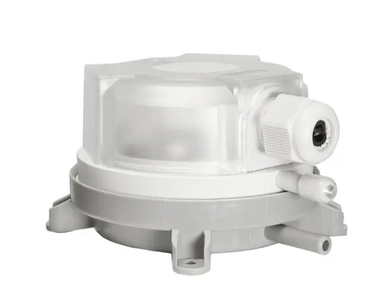
The LEFOO LF32 family comprises adjustable variants rather than a single universal range. The manufacturer's published variants include 20–200 Pa, 30–300 Pa, 50–500 Pa and higher ranges. The manufacturer identifies an SPDT switching arrangement and a setpoint adjustment scale; check the actual ordered variant and its tolerance before accepting any proposed threshold.
The current ProSense LF32 product listing shows selectable pressure ranges. Match the required setpoint to the filter manufacturer's documented terminal pressure drop, not to an arbitrary number copied from another building. Evaluate whether the switching differential and tolerance could cause nuisance alarms or late warnings.
3. Route both pressure tubes and mount the switch correctly
Use compatible tubes and fittings, with identified high-pressure and low-pressure connections. Protect each tube from crushing, kinks, leaks, condensation traps and abrasion. Manufacturer installation guidance warns that long tubes can slow response and that mounting orientation can influence the switching point. Follow the latest approved LF32 instructions for the selected unit.
A practical conceptual arrangement is: upstream filter tap to the high-side port, downstream filter tap to the low-side port, then the SPDT output to a suitable control or monitoring input. This is a logic example, not a wiring drawing. A qualified person must verify terminal selection, power isolation, contact electrical ratings and any protection needed by the receiving circuit.
4. Commission at the right operating conditions
Start with the approved air-handling-unit operating sequence, filter type and design airflow. Record the clean-filter differential pressure at an identified fan speed and damper state. If the fan is variable speed, test representative operating modes rather than assuming one pressure threshold performs identically at every airflow.
Use an appropriate reference manometer to verify actual differential pressure. Confirm the switch contact changes state at an acceptable measured value; then test the complete monitoring path, including wiring, input interpretation, indication, delay, notification and acknowledgement where these functions are independently provided by the site controls. Do not infer the presence of SMS, remote escalation or logging from the LF32 switch itself.
5. Worked example: threshold selection without guesswork
Consider a hypothetical air handler whose clean-filter pressure drop is 110 Pa at a documented commissioning airflow. Suppose the filter supplier specifies replacement assessment at a measured 240 Pa for that installation. A 30–300 Pa LF32 variant may be worth evaluating, but it must not be chosen solely because 240 Pa sits inside its nominal range.
Check the manufacturer-specified setpoint tolerance and switching differential, compare those values with the project's alarm margin, and run a controlled acceptance test using a reference instrument. If the required decision is too close to the tolerance band, select a more suitable monitoring method or revise the alarm design. These example numbers are illustrative, not LF32 performance guarantees or a recommendation for a particular filter.
6. Common faults that invalidate an apparently successful test
The most frequent diagnostic mistakes are swapping the high and low tubes, selecting a range that cannot sensibly resolve the desired threshold, setting the dial with the fan stopped, and omitting the alarm's end-to-end test. Another common problem is a contact that appears healthy in normal running but reports the wrong state when a wire breaks, a fan stops or controller power is removed.
Specify the normal contact state, any deliberate time delay and the action to take when readings or circuit continuity are ambiguous. A differential-pressure switch does not replace scheduled filter inspection, airflow commissioning or local operating procedures. Fire/smoke-control and other life-safety functions require separate qualified assessment and appropriate certified components.
7. When a continuous pressure transmitter makes more sense
An adjustable switch is useful for a local binary threshold. For historical trends, different thresholds by fan state or BMS analytics, a suitably selected differential-pressure transmitter may be more appropriate. The equipment must be selected for its actual output type and range; do not assume an LF32 switch provides 4–20 mA or Modbus communications.
For application scoping, compare the LEFOO LFM108 low differential-pressure transmitter/controller with the LF32 switch. Check the exact chosen LFM108 variant's output, supply, span and compatibility before designing any connected monitoring scheme. ProSense's HVAC monitoring solutions page provides broader application context; it is not proof of a preassembled LF32-to-dashboard kit.
8. Document the acceptance test and handover
The handover record should identify the filter and AHU, switch model and pressure-range variant, tapping positions, tubing route, reference instrument, baseline pressure drop, tested alarm setpoint, observed contact state, fan operating condition and responsible verifier. Include the cleaning or replacement criterion and who receives or investigates the alarm.
For manufacturer reference, consult the current LEFOO LF32 product and technical documentation. For an already published general overview, see ProSense's LF32 applications article. This commissioning guide focuses on site acceptance and failure-state checks rather than repeating the switch's general benefits.
Need help with your application?
ProSense Solutions can help your project team select a differential-pressure measurement approach for industrial HVAC, filtration and monitoring requirements. Discuss your project or request a quote with the AHU details, filter schedule, intended alarm threshold, available power, wiring distance and required reporting. Installation, electrical safety and any life-safety design must be assessed and completed by appropriately qualified parties.

