.png)
Flow Measurement for Wastewater and Sludge: Choosing the Right Meter
Wastewater, sludge and difficult industrial liquids rarely behave like clean water in a test lab. They can carry grit, fibres, fats, chemicals, air pockets and suspended solids. They may coat pipe walls, change density through the day, or move slowly enough for solids to settle in the line.
That creates a clear problem. A flow meter can only be as good as the application information behind it. The right technology, liner, electrode, pipe arrangement and transmitter setup all need to match the actual fluid, not just the nominal pipe size.
For conductive, dirty or solids-bearing fluids, two technologies often come into the discussion: electromagnetic flow meters and clamp-on ultrasonic flow meters. Each has strengths. Each has limits. The best choice depends on the process conditions, the pipework and the level of accuracy needed.

Why dirty and solids-bearing fluids are hard to measure
Clean liquids are predictable. Wastewater and sludge are not.
The fluid may be conductive, chemically aggressive, abrasive, aerated, sticky, or full of solids. It may include:
Sand and grit
Biological sludge
Fibres and rags
Food waste
Oils, fats and grease
Chemical dosing residues
Mining, paper, chemical or trade waste liquids
A meter must cope with the liquid itself and the way it moves through the pipe. Several issues cause trouble.
Solids can settle. If the velocity is too low, heavier material can drop out of suspension and build up along the bottom of the pipe. That reduces the effective area and causes unstable readings.
Air can pass through the line. Entrained air or partially full pipe conditions can make many meter types read high, low or erratically.
Coating can affect the measuring surface. Grease, scale, biological growth and sludge films may build up on liners or sensors.
The fluid can be abrasive or corrosive. A meter body, liner or electrode that works well in potable water may fail early in a harsh waste stream.
Access may be limited. Some plants cannot easily shut down a line, cut pipework, or drain a main to install a meter.
This is why flow measurement for wastewater and sludge starts with the application, not the catalogue page.
Electromagnetic flow meters suit conductive dirty liquids
Electromagnetic flow meters, often called mag meters, are a common choice for wastewater and many industrial liquids. They measure flow using Faraday’s law of electromagnetic induction. In simple terms, a conductive liquid moving through a magnetic field generates a voltage. The meter measures that voltage and converts it into flow velocity.
Because there is no obstruction in the bore, a mag meter is well suited to dirty liquids. There are no moving parts in the flow path, so there is less to wear, block or catch fibres.
Mag meters are often used for:
Raw sewage
Treated effluent
Return activated sludge
Waste activated sludge
Chemical waste streams
Conductive process liquids with suspended solids
The key requirement is conductivity. The liquid must be conductive enough for the meter to generate a usable signal. Most municipal wastewater applications meet this requirement, but some industrial liquids need closer checking.
Where mag meters perform well
A correctly specified mag meter can provide stable measurement in tough services. It handles many duties that would be difficult for turbine, positive displacement or paddlewheel meters.
The main advantages are:
Unobstructed bore
No moving parts in the fluid
Good performance with suspended solids
Bidirectional flow measurement if configured
Suitable for many pipe sizes
Available with remote transmitters for flooded, hot or hard-to-access areas
Mag meters also work well where pressure loss must be kept low. Since the bore is open, the meter does not add a major restriction.
Where mag meters need care
Mag meters still need correct installation. They are not immune to bad pipework.
They normally need a full pipe. If the pipe runs partly full, the meter may read incorrectly because the electrodes are not properly covered and the cross-sectional area is not what the meter assumes.
They also need a stable velocity profile. Disturbances from elbows, valves, pumps, reducers or partially open control valves can upset flow patterns. A well-planned installation uses enough straight pipe before and after the sensor, according to the meter manufacturer’s requirements.
Mag meters also need good grounding. Poor grounding can introduce noise into the measuring circuit, especially in plastic-lined pipe, non-conductive pipe, or electrically noisy industrial sites.

Liners and electrodes must match the liquid
A mag meter body does not directly contact the liquid through bare metal. The inside of the measuring tube has a liner. The electrodes pass through the liner and contact the liquid to pick up the measurement signal.
For dirty and industrial liquids, the liner and electrode materials matter as much as the electronics.
Common liner considerations
The liner must resist the fluid, the temperature and the mechanical conditions.
Typical liner choices may include rubber, polyurethane, PTFE or other specialist materials, depending on the meter design and application. The right option depends on what the liquid contains.
For example:
Application condition | Liner concern |
Grit or abrasive solids | Resistance to wear |
Chemicals or trade waste | Chemical compatibility |
Hot liquids | Temperature rating |
Sludge with coating risk | Surface behaviour and cleanability |
Vacuum or pressure cycling | Mechanical stability |
No single liner is best for every wastewater or sludge duty. A rubber liner may suit many general wastewater applications, while a chemically aggressive industrial liquid may call for a different material. Abrasive slurry may need a liner chosen mainly for wear life.
Electrode material and shape matter
Electrodes need reliable contact with the liquid. In wastewater duties, they may face coating, chemical attack and abrasion.
Electrode materials can include stainless steel, Hastelloy, titanium, tantalum or other options, depending on the fluid chemistry. The selection should be based on the actual liquid, not only the plant area name.
Electrode style can also help. Some meters offer specialised electrodes for coating-prone liquids or low-conductivity service. Others may include empty pipe detection electrodes or diagnostics to identify unstable conditions.
The main point is simple: the wetted materials must suit the worst credible operating condition. That includes cleaning chemicals, batch discharges, temperature swings and unusual waste events.
Clamp-on ultrasonic meters are useful when cutting the pipe is difficult
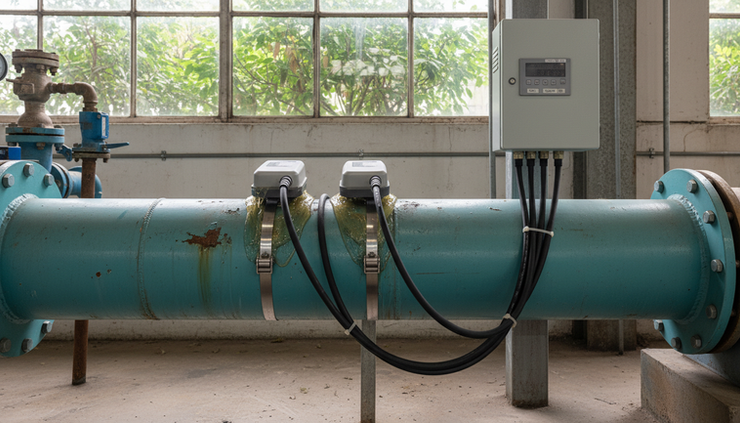
Clamp-on ultrasonic flow meters sit outside the pipe. They send sound signals through the pipe wall and liquid, then calculate flow from the signal behaviour. Since the sensors do not touch the liquid, they are attractive when the line cannot be cut or the fluid is aggressive.
They can be useful for:
Temporary flow surveys
Checking existing meters
Large pipes where insertion is costly
Corrosive liquids that are hard on wetted parts
Sites where shutdown access is limited
Clean to moderately dirty liquids where the signal can pass through the pipe and fluid
Clamp-on meters are often considered because installation can be faster and less intrusive than an inline meter. They can be a practical way to get flow data from an existing pipe without major mechanical work.
Transit time and Doppler measurement
Clamp-on ultrasonic meters commonly use transit time or Doppler principles.
Transit time meters compare the travel time of ultrasonic signals sent with and against the flow. They usually work best with liquids that are relatively clean and have a stable sound path.
Doppler meters rely on reflected signals from particles or bubbles in the fluid. They can suit some dirty or aerated liquids, but need enough reflective material in the liquid and a signal path that remains usable.
For wastewater and sludge, the fluid may help or hurt the measurement. Suspended solids can support Doppler measurement, but heavy attenuation, thick sludge, poor pipe condition or excessive air can make the signal unreliable.
Pipe condition is critical
Clamp-on ultrasonic performance depends on the pipe as much as the fluid. The signal has to travel through the pipe wall, any lining, the liquid and back again.
Important factors include:
Pipe material
Pipe outside diameter
Wall thickness
Liner type and thickness
Pipe age and corrosion
External coating condition
Whether the pipe runs full
Available straight lengths
Fluid sound properties
A clamp-on unit installed on a heavily corroded, lined or scaled pipe may struggle, even if the meter itself is suitable. Good coupling, correct sensor spacing and a clean mounting area are essential.
Pipe arrangement can make or break the measurement
A good meter in bad pipework can still give poor results. Wastewater and sludge services need pipe arrangements that keep the line full, limit turbulence and prevent solids from settling.
Full pipe conditions come first
Most closed-pipe flow meters assume the pipe is full. That is especially true for mag meters. The best installations avoid high points where air collects and avoid downward discharge points where the pipe may run partially full.
Good locations often include:
Vertical upward flow
Low points that stay flooded
Horizontal runs with stable back pressure
Sections away from free discharge
Risky locations include:
Downward vertical flow without enough back pressure
High points in the line
Immediately after a pump outlet
Immediately before open discharge
Lines with siphoning or draining behaviour
For sludge, vertical upward flow can be useful because it helps keep solids suspended. Horizontal runs may still work well, but velocity and pipe condition need attention.
Straight pipe helps the meter see a stable profile
Elbows, tees, pumps and valves disturb the flow profile. The meter may see swirl, asymmetric velocity or pulsation instead of smooth flow.
Manufacturers give minimum upstream and downstream straight pipe requirements. These should be treated as part of the specification, not as a suggestion to check after installation.
When the site cannot provide ideal straight lengths, ProSense needs to know the exact arrangement. A less ideal position may still work, but it may need a different technology, a flow conditioner, different sizing, or a realistic accuracy expectation.
Valves and pumps need careful placement
Control valves can create strong turbulence, especially when partly closed. Where possible, place the flow meter upstream of a control valve rather than directly downstream.
Pump discharge lines can carry pulsation, swirl and entrained air. A meter near a pump may need extra straight length, stable back pressure, or a different location.
For sludge, pump type also matters. Progressive cavity, centrifugal, diaphragm and peristaltic pumps produce different flow patterns. This can affect meter stability.
Correct sizing is not just matching the pipe size
One of the most common mistakes is choosing a meter only by nominal pipe diameter. A DN150 pipe does not always need a DN150 meter.
The meter must suit the expected velocity range. If the pipe is oversized and the flow is low, the velocity may fall below the ideal range for accurate and stable measurement. Solids may also settle.
In some cases, a smaller meter with reducers may give better results, provided the pressure loss, solids handling and installation rules allow it. In other cases, reducing the bore would create too much risk of blockage or wear.
The sizing process should account for:
Minimum, normal and maximum flow rates
Pipe size and pipe schedule
Fluid velocity
Solids content and particle size
Risk of settling
Pressure available
Required accuracy
Future flow changes
For sludge and difficult liquids, the normal flow rate may be more valuable than the pump’s theoretical maximum. A meter that only performs well at rare peak flow may be unstable during everyday operation.
Grounding protects the signal on mag meters
A mag meter measures a small electrical signal generated by the conductive liquid. That signal can be affected by electrical noise, stray currents or poor reference to earth.
Grounding gives the meter a stable electrical reference. The exact method depends on the pipe material and installation.
Common grounding arrangements include:
Pipe arrangement | Common grounding approach |
Conductive unlined metal pipe | Grounding through pipe flanges may be suitable if bonding is sound |
Plastic or non-conductive pipe | Grounding rings or grounding electrodes are often required |
Lined metal pipe | Grounding rings may be needed because the liner insulates the liquid |
Cathodically protected pipe | Special attention is needed to avoid interference |
Poor grounding can look like a bad meter. Symptoms may include noisy readings, drifting zero, unstable output or unexplained signal faults.
Grounding should be planned before installation. It should not be treated as a quick fix after commissioning problems appear.

Remote transmitters help in wet, hot or awkward locations
Many mag meters are available with either compact or remote transmitters.
A compact transmitter mounts directly on the flow sensor. This can be neat and simple where access is good and the environment is suitable.
A remote transmitter mounts away from the sensor and connects by cable. This can be the better choice when the pipe location is:
Flood-prone
Hard to access
Subject to vibration
Too hot for electronics
In a pit or chamber
Exposed to washdown or chemical splash
Better served by a display at operator height
Remote transmitters also make maintenance easier in some plants. Staff can view flow, check diagnostics and access wiring without entering a confined or wet area, subject to site safety rules.
Cable selection and routing still matter. Signal cables should follow manufacturer guidance, especially for longer runs and electrically noisy areas.
What ProSense needs before specifying a meter
A reliable specification starts with clear fluid and site information. Guesswork can lead to the wrong meter, wrong liner, wrong electrode material, or wrong size.
When ProSense specifies a meter, the most useful information includes:
Fluid name and description
Conductivity, if known
Solids type, size and percentage
Grit, fibre, ragging or grease content
Minimum, normal and maximum flow rates
Pipe material, size and wall thickness
Liner material, if the pipe is lined
Pressure and temperature
Chemical compatibility details
Whether the pipe always runs full
Pump and valve locations
Available straight pipe lengths
Installation environment
Power supply and output signal needs
Local display or remote transmitter preference
Photos and sketches are often valuable. A simple pipe sketch showing bends, pumps, valves, reducers and discharge points can prevent costly mistakes. For clamp-on ultrasonic applications, pipe wall thickness and material are especially important.
For mag meters, fluid conductivity, grounding conditions and wetted material compatibility are key. For sludge, expected velocity and solids behaviour deserve close attention.
Choosing between electromagnetic and clamp-on ultrasonic meters
Both technologies can be excellent when used in the right place.
Requirement | Electromagnetic meter | Clamp-on ultrasonic meter |
Conductive wastewater | Often a strong choice | Possible, depending on pipe and fluid |
Thick sludge | Often suitable with correct sizing and materials | Can be difficult if signal is heavily attenuated |
No pipe cutting allowed | Requires pipe work | Strong advantage |
Long-term custody-style monitoring | Often preferred where conditions suit | Possible on suitable pipework, but site dependent |
Corrosive fluid | Wetted materials must be selected carefully | Sensors do not contact the liquid |
Poor pipe condition | Inline installation may bypass some issues | Can be a major limitation |
Temporary flow check | Less convenient | Often useful |
Partly full pipe | Usually unsuitable | Usually unsuitable for closed-pipe clamp-on measurement |
The practical choice often comes down to this:
Choose a mag meter when the liquid is conductive, the pipe can be modified, a full pipe is available, and a durable long-term measurement is needed.
Consider clamp-on ultrasonic when access to the liquid is undesirable, shutdown is difficult, or a temporary or non-intrusive measurement is needed.
Neither option removes the need for good installation. A mag meter with poor grounding can disappoint. A clamp-on ultrasonic meter on a poor pipe surface can also disappoint.
A sound specification prevents expensive rework
Wastewater, sludge and difficult industrial liquids put flow meters under real pressure. The fluid may be dirty, conductive, abrasive, aerated and chemically variable, all in the same plant. That is why meter selection needs more than a pipe size and a flow estimate.
The best results come from matching the technology to the liquid, sizing the meter for the real flow range, choosing the right liner and electrodes, confirming the pipe runs full, planning grounding, and installing the sensor in suitable pipework.

A well-specified meter does more than produce a number on a display. It gives operators trusted flow data for process control, compliance reporting, pump performance checks and plant improvement work. For dirty liquids, that trust starts before the meter is ordered, with accurate fluid information and a clear picture of the installation.


