
Cooling-Water Flow Monitoring: Clamp-On Surveys, Permanent Meters and Alarms
Cooling-water systems rarely fail because a temperature display alone looks unusual. Poor circulation, a partly closed valve, a fouled strainer, a bypass left open or a pump running outside its intended operating point can all affect cooling capacity. A useful flow-monitoring project therefore begins with decisions the maintenance team needs to make, not with a meter catalogue.
This guide explains how to plan a practical ProSight Flow measurement solution for chilled-water circuits, equipment cooling, heat exchangers, plant rooms and industrial process loops. It covers temporary measurement, permanently installed meters, signals, totalisation and alarms. It is an engineering selection guide—not a claim that one instrument suits every site.
Cover image: illustrative industrial water-treatment equipment. It is not a photograph of a ProSense customer installation.
1. Start with the cooling circuit, not the transmitter
Identify the supply header, return header, each major branch, bypasses, critical heat exchangers, isolation valves, strainers and available instrument points. Record which pumps run continuously, which are staged or variable-speed, and when low flow should trigger an operational response. On an existing plant, separate the intended flow path from temporary commissioning bypass arrangements.
For every proposed measurement point, define the question it answers. Is the aim to prove minimum flow through a machine, compare distribution between branches, reconcile make-up water, measure weekly volume, verify a pump change, or observe a process remotely? A single totaliser at the common header may miss a blocked branch; several branch meters without a clear alarm policy can create unnecessary complexity.
Specify the liquid before specifying a measuring principle. Chilled-water loops may contain treatment chemicals or glycol blends, which change acoustic performance, viscosity, electrical conductivity and the relationship between flow and thermal energy. Confirm concentration, operating temperature, pressure and the process safety requirements rather than assuming the circuit contains clean water.
2. Match the measurement method to the job
Clamp-on ultrasonic: useful for a first survey
Transit-time ultrasonic transducers are attached to the outside of a suitable pipe and can measure flow without opening the process. They are attractive for temporary audits or retrofits where shutdown is difficult, but successful measurement depends on the acoustic path, pipe material and thickness, internal diameter, lining, liquid characteristics and a sufficiently full pipe. Aeration, deposits or unsuitable fluid conditions can affect performance.
Use a portable clamp-on survey to compare operating modes, locate suitable permanent meter positions and observe the effects of pump-speed changes. Do not assume a survey instrument will achieve its published accuracy on every pipe; validate against the exact manufacturer's installation and commissioning guidance.
Inline electromagnetic: for compatible conductive liquids
An electromagnetic meter can be a strong permanent choice for water and other suitably conductive process liquids. However, it requires a compatible wetted construction, appropriate conductivity, electrical grounding and the specified installation orientation and straight runs. A pipe break or planned installation shutdown is normally necessary for a full-bore flanged meter. Check liner, electrode materials, pressure and temperature against treatment chemistry.
Electrical conductivity is particularly important for treated water and certain glycol mixtures. An electromagnetic flowmeter is not a universal answer for oils or very low-conductivity liquids. The selected meter's conductivity threshold and process-fluid compatibility must come from its datasheet.
Insertion or turbine alternatives: application-dependent
Insertion ultrasonic and insertion electromagnetic models can suit certain large pipelines or retrofit circumstances, but the installation requires compatible access, safe process isolation, representative velocity profile and appropriate insertion depth. The chosen technology and fitting affect shutdown work and long-term maintenance. Turbine meters may be viable for clean compatible liquids, but moving parts and contamination or wear should be considered. None of these methods should be selected solely on purchase price.
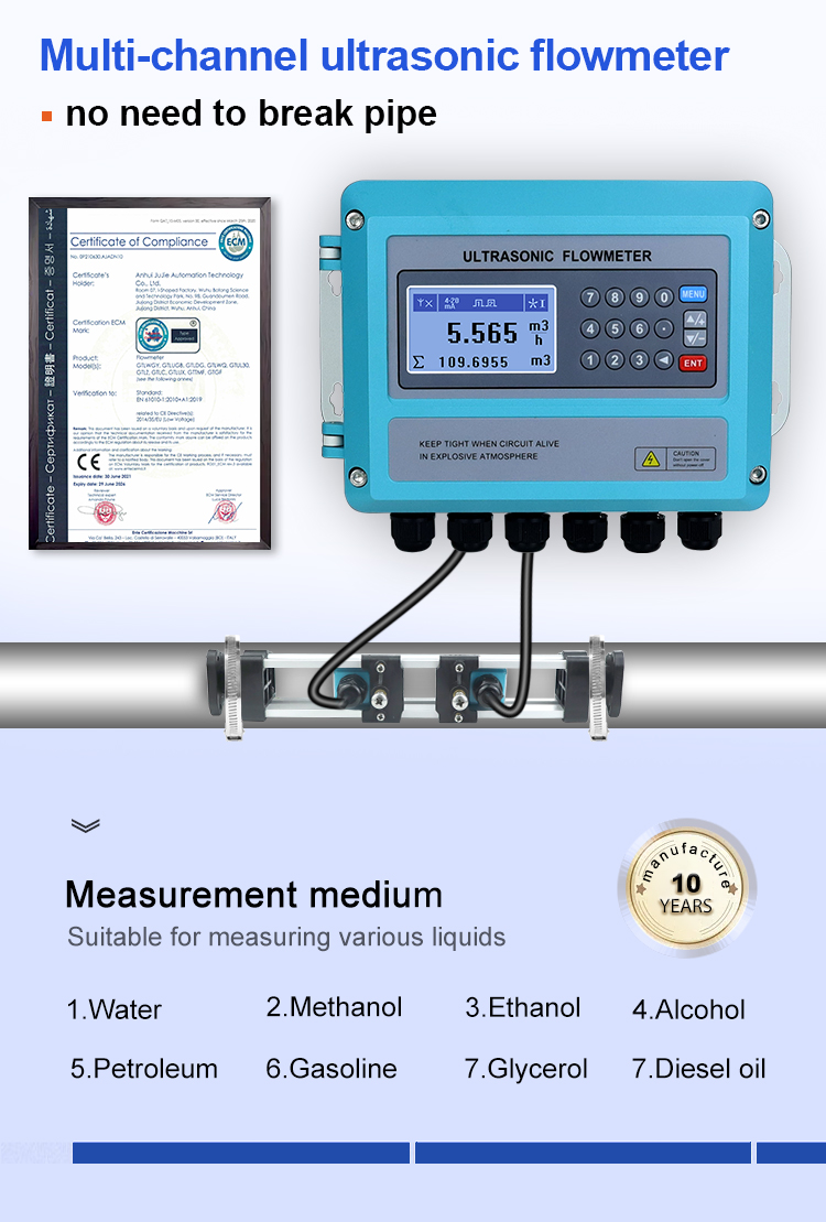
Image note: Actual catalogue product image from ProSense's clamp-on ultrasonic flowmeter listing. The picture does not establish compatibility with a particular cooling-water pipe, glycol blend or output configuration.
Explore the ProSense clamp-on ultrasonic flowmeter range and confirm the specific product's pipe, liquid and signal requirements before selection.
Review an insertion ultrasonic flowmeter listing for an alternative that may suit selected installations.
Review the ProSense electromagnetic flowmeter listing for conductive-liquid applications.
3. The site survey checklist
Liquid: identify water chemistry, glycol concentration if present, solids, air entrainment and conductivity where relevant. Pipe: document external diameter, internal diameter, schedule, material, lining, insulation, surface condition and accessible straight length. Process: record normal and maximum flow, expected minimum when each pump is running, flow direction, operating pressure and temperature.
Installation: confirm space for the transducer or meter body, full-pipe conditions, distance from valves, elbows and pumps, electrical isolation, earthing and potential shutdown windows. Process disturbances can distort the velocity profile. There is no defensible universal straight-run distance: use the selected meter's installation manual and check upstream and downstream restrictions.
Measurement and reporting: decide whether the operator needs instantaneous litres per second, cubic metres per hour, accumulated cubic metres, pump efficiency investigations, network telemetry or a plant-control input. Accuracy, repeatability, flow-range limits, turndown and display resolution should be specified separately. A display with many decimal places does not itself establish accurate flow measurement.
Manufacturer guidance on clamp-on installation and full-pipe conditions is useful background; final clearances and mounting details must still come from the exact chosen model.
4. How a connected flow-monitoring architecture works
The basic information path is: correctly installed meter → validated output signal → suitable PLC, logger or remote telemetry unit → local or cellular/network connection → dashboard, reports and notifications. The meter remains the primary measurement source; cloud software cannot correct a poor installation or an incorrectly scaled signal.
A pulse output can represent incremental volume and may be convenient for totalisation when the pulses-per-unit factor is confirmed. A 4–20 mA output usually represents an instantaneous engineering range and needs correct scaling at the receiving instrument. RS485/Modbus can carry process values and status where the particular meter, register map and receiver support it. Check signal isolation, power, addressing, baud rate, register type, data order, communications timeout and grounding as applicable. Output options vary by model and configuration.

Image note: Conceptual industrial monitoring network illustration only—not a verified wiring diagram or a confirmed compatibility map. The actual meter, logger, gateway and destination must be selected and checked as a system.
ProSense can help select a monitoring architecture around the site requirements, including locally recorded values, appropriately specified remote telemetry, alarm outputs and data dashboards. The final choice depends on device support, communications coverage, cyber-security needs and data-retention requirements. Do not assume that a 4G, LoRaWAN or Modbus product automatically connects to every dashboard.
Read the companion guide to 4G, LoRaWAN and RS485 flow-monitoring architectures for a deeper look at telemetry planning.
5. Totalisation, cooling performance and useful alarms
Flow rate and total volume answer different questions. Flow rate shows what is happening now; a totaliser accumulates volume over a stated period. Where the source is a pulse meter, record the verified pulse factor and protect against missed counts. Where software derives total volume from sampled flow, document sample intervals, units, missing values and the treatment of communication gaps. A frozen zero or a stale last-known value must not silently distort reporting.
For cooling performance, flow alone is not a heat-transfer measurement. Estimating heat transfer also requires paired supply and return temperatures and appropriate fluid density and specific heat capacity, particularly for glycol mixtures. Trend analysis should distinguish confirmed sensor values from derived performance estimates.
Useful alarms are operationally conditional. For example, low flow may matter only when a pump is commanded on; zero flow with every pump stopped may be normal. Consider low flow during a running period, unexpected sustained high flow, flow when the circuit should be isolated, abnormal total use over a shift, signal failure and telemetry data that has stopped updating. Add sensible delay and hysteresis to avoid nuisance alarms during starts, valve transitions and pump staging.

Image note: Illustrative dashboard image, not a live ProSight Software screenshot or a customer installation. Actual flow, volume, pump-state and alarm tiles depend on the selected hardware and software design.
A practical operator dashboard separates live flow, daily and weekly volume, pump running state and signal health. It should clearly flag missing data rather than treating a communication outage as a genuine zero-flow event. An alarm needs a designated recipient, escalation process and operator response—not just a red symbol on a screen.
6. Commissioning and maintenance are part of measurement quality
Before handover, verify the measured pipe dimensions, liquid settings, mounting positions, direction and flow units. Compare readings at stable operating points against a credible reference or expected process range, where feasible. Record the meter configuration and calibration status. If a pulse totaliser or analogue scaler is used, independently check that the receiving instrument reports the intended engineering units.
Test conditions that matter: pump off, pump starting, low-flow operating mode, normal stable operation, data disconnection, alarm acknowledgment and return to service. Confirm who will adjust thresholds when equipment or duty cycles change. Preserve a commissioning record so later differences between instruments can be investigated rather than guessed.
Maintenance expectations differ between non-intrusive transducers, full-bore instruments and insertion devices. Plan inspections for coupling condition, instrument grounding, liner or electrode fouling where applicable, process isolation and firmware or communications changes. The absence of moving parts in some technologies does not make them maintenance-free.
7. A better procurement brief for a cooling-water project
An effective request for quotation specifies: the liquid and treatment chemistry; pipe diameter, material and wall thickness; temperature and pressure; minimum, normal and peak flow; available straight pipe; permanent versus temporary measurement; required accuracy and signals; local power and network availability; need for totalisation, alarms and dashboard access; and whether a shutdown or pipe penetration is possible.
ProSight Flow provides ProSense's starting point for selecting suitable liquid-flow instrumentation and connected monitoring components. The right choice may be clamp-on for an audit, a permanent electromagnetic meter for verified conductive water, or an appropriate insertion/inline solution for other constraints. The choice is established by application data and verified product documents—not by a generic flowmeter label.
Discuss your cooling-water measurement application with ProSense Solutions and provide the site survey details above for a practical equipment recommendation.
Further reading and technical sources
Editorial note: equipment names, output protocols and measurement methods are described at a family level. Pipe, liquid, signal, installation and accuracy specifications must be verified against the ordered model and revision before project design.


