.png)
Wireless Current Monitoring for Motors Pumps and Machinery
A motor can look normal from the outside while its electrical behaviour tells a different story. It may be running longer than expected, stopping when it should be operating, or drawing more current than usual under load. Without current data, those changes often stay hidden until production slows, a pump runs dry, or a fault becomes expensive.
Wireless AC current monitoring gives maintenance and operations teams a practical way to see whether key equipment is running, stopped, or operating outside expected current levels. Monnit wireless AC current meters can support this by measuring current and sending readings to a dashboard without running signal cable back to a controller or data logger.
For motors, pumps, fans, compressors and other machinery, that data can help answer simple but valuable questions:
Is the machine actually running?
How many hours has it operated this week?
Is current draw higher or lower than expected?
Did it start when it was meant to?
Has its load changed over time?

What wireless AC current monitoring measures
A wireless AC current meter measures the current flowing through an electrical conductor. In many installations, this is done with a current transformer, often called a CT, placed around one conductor feeding the equipment.
The sensor does not need to measure every part of the electrical system to be useful. For many applications, a current reading on the correct conductor is enough to identify whether a motor is:
Off
Running under normal load
Running under light load
Drawing unusually high current
Cycling on and off more often than expected
That makes wireless current monitoring useful for equipment state detection as much as electrical measurement. It turns current draw into a practical operational signal.
For example, a pump with a normal running current band can be watched for readings outside that range. A fan that should run during production hours can be checked against a time schedule. A machine that is hard to access can report operating status without someone walking to the site.
Monnit wireless AC current meters are designed for this kind of remote visibility. They send readings wirelessly to a gateway, which passes data to an online system where users can view trends, set alerts and check equipment status.
Why current data is useful for motors, pumps and machinery
Current is not a complete picture of machine health, but it is one of the most useful signals to start with. It often changes when the way a machine is operating changes.
A motor under a heavier mechanical load will usually draw more current. A pump that loses prime or runs against a restriction may show a different current pattern from normal operation. A conveyor that jams, drags or starts more often than expected may show higher peaks or longer run times.
This data can support several common maintenance and operations tasks.
Equipment utilisation studies
Many facilities have machines that are assumed to be busy because they are critical or noisy. Current monitoring can show the actual operating pattern.
That matters when planning upgrades, scheduling maintenance, or checking whether a process is using equipment efficiently. A motor that runs only a few hours a day may not need the same maintenance schedule as one that runs almost continuously. A standby pump that starts often may need closer review.
Utilisation data can also help identify mismatch. If a motor is rarely loaded, the equipment may be oversized for the task. If a pump runs for long periods without reaching process demand, the issue may sit elsewhere in the system.
Operating-hour tracking
Many service schedules are based on run hours rather than calendar time. Oil changes, belt inspections, bearing checks and filter replacements can all be affected by how much a machine actually operates.
Wireless current readings can help estimate operating hours by identifying when current rises above an agreed running threshold. Over time, the dashboard can show how often the machine has run and for how long.
This is especially helpful for remote or distributed assets, such as:
Bore pumps
Sump pumps
Ventilation fans
Transfer pumps
Packaged plant
Irrigation equipment
Small production machines
Instead of relying on manual logs or best guesses, teams can build a clearer record of actual use.
Basic condition monitoring
Current monitoring is not the same as vibration analysis, thermography or motor circuit testing. It will not diagnose every fault. It can, though, provide an early sign that something has changed.
A rising current trend may point to increasing load, mechanical drag, a blockage, poor alignment, bearing wear, or process changes. A sudden drop may indicate a loss of load, a broken belt, a dry-running pump, or a machine that has stopped doing useful work.
The value comes from comparing current against the machine’s normal pattern. Once that pattern is known, alerts can be set for readings that sit outside expected levels.

Where this type of monitoring fits best
Wireless current monitoring works well where the goal is to get useful machine status without building a full control system.
It is a good fit for existing equipment because it can often be added without major changes to the machine. The wireless sensor can be placed near the electrical supply, with data sent back through the gateway. That can reduce the need for long signal cable runs, especially across a plant, yard or distributed site.
Common use cases include:
Application | What current monitoring can show | Useful alert example |
Pump motors | Running, stopped, dry-running signs, high load | Pump did not start during scheduled period |
Exhaust or supply fans | Operating hours and unexpected stoppages | Fan current below running threshold during shift |
Conveyors | Run time, load changes, frequent cycling | Current above normal band for several minutes |
Compressors | Start patterns and operating hours | Compressor running outside expected hours |
Mixers and agitators | Load changes during process cycles | Current lower than expected during a batch |
Remote machinery | Status without a site inspection | No current detected when equipment should be active |
The best applications have a fairly stable relationship between current draw and operating state. If the current level changes clearly when the machine starts, stops or loads up, the sensor has a strong signal to work with.
Single-phase and three-phase options
Some equipment only needs one current measurement to answer the main question. A single-phase load, for example, may be monitored with one correctly rated current sensor on the active conductor.
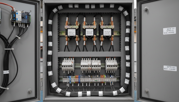
Three-phase machinery can be more complex. Depending on the application, monitoring one phase may be enough to detect run status. In other cases, a three-phase current-meter option may give a better view of load balance and operating behaviour.
Three-phase current-meter options are available for suitable industrial applications. The right choice depends on the equipment, supply arrangement, current range, enclosure space and the level of detail required.
A basic run or stop signal may only need a simple setup. A more critical pump or process motor may justify more detailed measurement and alerting.
The key is to match the monitoring method to the question being asked. If the question is “did the pump run?”, the setup may be simple. If the question is “is this three-phase motor drawing evenly and within its expected operating range?”, the sensor choice and installation plan need more care.
Choosing the right current range
Current range is one of the most important selection points. A sensor must suit the equipment’s expected current draw.
If the range is too low, readings may exceed the sensor’s capacity. If the range is too high, the readings may not give enough detail at normal operating levels. The goal is to select a range that covers normal running current, expected peaks, and any alert thresholds that matter.
Useful information for sensor selection includes:
Equipment type
Supply voltage and phase arrangement
Full-load current from the nameplate
Typical running current, if known
Starting behaviour
Whether the load varies during operation
The main monitoring goal
The physical space available for CT placement
For motors, the nameplate full-load current is often the starting point, but it is not always the full story. Some machines run well below nameplate current most of the time. Others may experience changing loads through each cycle.
ProSense can help match the sensor and current range to the equipment, then configure dashboards and alerts for real operating conditions. That matters because the hardware is only one part of the system. The thresholds, reporting interval and alert logic also need to fit the machine.
Setting useful dashboards and alerts
A dashboard should answer practical questions quickly. It should not become a screen full of numbers that nobody uses.
For current monitoring, good dashboards often show:
Live current reading
Running or stopped status
Recent trend
Daily or weekly run hours
Alert state
Last communication time
Battery or device status, where available
The best alert settings come from normal operating data. A short baseline period can show the usual current range for each machine. From there, high and low current alerts can be set with enough margin to avoid nuisance messages.
Common alert types include:
No-run alert
This triggers when current stays below the running threshold during a period when the machine should operate.
Unexpected-run alert
This triggers when current rises above the running threshold outside expected operating times.
High-current alert
This triggers when current remains above a set level for longer than a short starting period.
Low-current while running alert
This can help detect loss of load, such as a broken belt or pump issue, where the motor is energised but not doing normal work.
Excessive run-time alert
This triggers when the equipment runs longer than expected, which may point to a process issue or control fault.
Alert delays matter. Motors can draw a higher current during starting, and some loads naturally fluctuate. A practical alert should allow for normal behaviour while still catching real problems.
What installation involves
Wireless current monitoring is often simpler than wired monitoring from a data cabling point of view, but the electrical installation still needs proper planning.
A current transformer must be placed in the correct location, around the correct conductor, and in the correct orientation where that matters. The installation should allow for safe access, suitable mounting and ongoing inspection.
Electrical installation and current-transformer placement must be completed by appropriately qualified personnel.
This is not just a compliance point. Incorrect placement can give misleading readings. Unsafe work inside switchboards or control panels can also create serious risk.
Planning should cover:
Where the CT will be fitted
Whether the enclosure has enough space
How the sensor will be mounted
Whether the wireless signal can reach the gateway
How the device will be labelled
Who will receive alerts
How data will be reviewed after commissioning
For remote plant, gateway placement needs the same attention as sensor selection. Wireless performance is affected by distance, metal enclosures, walls, machinery and site layout. A site check can help avoid weak communication paths.

Turning current readings into better decisions
The real benefit appears once current data becomes part of routine maintenance and operations review.
A trend that shows rising current over weeks can prompt an inspection before a machine trips. A run-hour total can prove whether an asset is due for service. A no-run alert can reveal a failed starter, control issue or tripped supply before someone notices a process problem.
Wireless monitoring also helps when equipment is spread across a large site or multiple locations across Australia. Instead of sending someone to confirm whether a pump has run, the system can show the latest current data and alert history.
This does not replace skilled maintenance work. It gives that work better timing and better context.
For example, if a pump has triggered several high-current alerts, the maintenance team can inspect it with a clearer starting point. If a fan has not run during its scheduled window, operations can check the control signal, starter, supply and airflow path. If a compressor is running outside normal hours, the team can look for demand, leaks or control settings.
A practical way to start
The best first project is usually one or two machines where the value is obvious. Pick equipment that is important, hard to check manually, or tied to recurring uncertainty.
Good starter assets include:
A critical transfer pump
A hard-to-access exhaust fan
A standby pump that should only run occasionally
A machine with unclear operating hours
A motor where high current has caused trips before
Start with a clear question. “Is it running?” is a valid question. So is “how many hours did it operate this month?” or “does current rise before it trips?”
Once the first installation proves useful, similar monitoring can be rolled out to other motors, pumps and machinery. The same dashboard structure and alert logic can often be adapted, with current ranges and thresholds set for each asset.
The takeaway
Wireless current monitoring gives a practical view of machinery that is often missing from daily operations. It can show whether equipment is running, stopped or drawing an unusual level of current, then turn that information into dashboards, alerts and operating-hour records.
Monnit wireless AC current meters are well suited to this role, including options for suitable three-phase industrial applications. With the right sensor range, correct CT placement and sensible alert settings, current data can support utilisation studies, maintenance planning and basic condition monitoring.
The smartest place to begin is with one asset where knowing the running state would save time, reduce uncertainty or help prevent avoidable downtime. From there, current monitoring can become a simple, useful layer of visibility across motors, pumps and machinery.


