.png)
Transform 4 20 mA Pulse and RS485 Instruments into Cloud Dashboards and Alarms with Battery and Solar Power
Most industrial sites already have valuable measurement data in the field. The problem is that much of it stays trapped in local gauges, PLC inputs, chart recorders, and RTU cabinets. Pressure, level, temperature, and flow transmitters may be working well, yet the data is not visible to operators unless they visit the site or connect through existing control systems.
A practical cloud data project does not always need new instruments. In many cases, the fastest path is to connect existing 4–20 mA, pulse, and RS485 devices to battery or solar-powered telemetry units. These units read the signal, time-stamp the value, send it over a cellular or other wireless network, then present it in dashboards with alarms, trends, and reports.
That approach suits remote tanks, pump stations, stand-alone flow meters, rental skids, treatment plants, irrigation assets, and utility networks across Australia, where mains power and fixed networks are often unavailable or expensive to extend.

Start with the signal type you already have
Before choosing a gateway or telemetry device, identify what the installed instrument actually provides. Many field devices use familiar industrial outputs, but each signal type has different wiring, power, and configuration needs.
Signal type | Common instruments | What the telemetry unit reads | Key design point |
`4–20 mA` analogue | Pressure, level, temperature, flow | A current proportional to the process value | Confirm loop power, scaling, and fault behaviour |
Pulse output | Water meters, gas meters, batch counters, rain gauges | Contact closures or voltage pulses | Confirm pulse value, maximum pulse rate, and debounce needs |
RS485 | Smart transmitters, flow computers, power meters, analysers | Digital registers, often via Modbus RTU | Confirm protocol, slave ID, baud rate, parity, and register map |
4–20 mA works well for continuous values
A 4–20 mA signal is simple, noise-tolerant, and still widely used. A pressure transmitter might output 4 mA at 0 kPa and 20 mA at 1,000 kPa. A level transmitter might output 4 mA at an empty tank and 20 mA when full.
A telemetry unit can read that current directly if it has an analogue input. Some units also provide loop excitation, which is useful when the field instrument has no local power. Others sit in series with an existing powered loop, which is useful when the transmitter already reports to a PLC or local display.
The main questions are:
Is the instrument loop-powered or separately powered?
Can the telemetry unit share the existing loop without affecting the control system?
What range does 4 mA and 20 mA represent?
What value should the cloud platform show below 4 mA or above 20 mA?
Does the transmitter use 3.6 mA or 22 mA to indicate a fault?
Pulse inputs are ideal for totals and rates
Pulse outputs appear on many flow meters. A meter may provide one pulse per litre, one pulse per 10 litres, or one pulse per cubic metre. A telemetry unit counts those pulses to calculate total volume and, when needed, flow rate.
Pulse integration is simple when the flow is steady. It needs more care when pulse rates are high, cables are long, or the pulse source is a reed switch that can bounce. Good telemetry units allow input filtering, pulse scaling, and counter rollover handling.
For billing, compliance, or custody transfer, keep the certified meter as the source of truth. Use the cloud system for visibility, alarms, and operations unless the full measurement chain has been approved for the required purpose.
RS485 gives access to richer data
RS485 is a physical communications layer, not a measurement protocol by itself. In industrial work, it often carries Modbus RTU. A single RS485 connection can read multiple values from one device, such as flow rate, totaliser, temperature, pressure, diagnostic status, and alarm flags.
This makes RS485 useful for smart flow meters, multi-parameter instruments, variable speed drives, packaged plant, and analysers. The trade-off is configuration. You need the device address, serial settings, register numbers, data types, and scaling factors.
Build the connection in a clear sequence
A cloud integration project works best when treated as an instrument loop job first and an IT job second. Start at the sensor, prove the signal, then add communications.
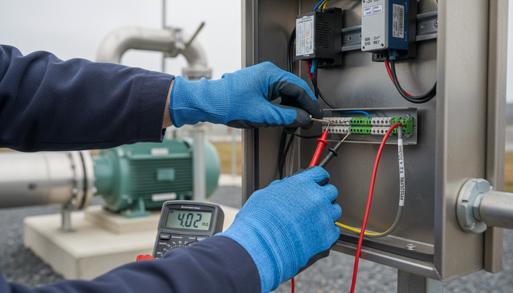
Step 1. Confirm the measurement and engineering range
Record the instrument tag, measured variable, units, and range. Do this before touching the wiring.
For example:
Pressure transmitter
Range 0 to 1,600 kPa, output 4–20 mA
Hydrostatic level transmitter
Range 0 to 6 m water, output 4–20 mA
Turbine flow meter
Pulse value 1 pulse per 10 L
Magnetic flow meter
RS485 Modbus RTU, flow rate and totaliser registers available
This step avoids a common cloud dashboard problem, where the signal is technically connected but the displayed value is wrong because the scaling is guessed.
Step 2. Check power availability and duty cycle
The power design depends on how often the unit wakes, reads, transmits, and sleeps.
A mains-powered site can send frequent updates. A battery-powered site may send every 15 minutes, hourly, or on change of value. A solar-powered site can send more often, but still needs a battery sized for poor weather and winter conditions.
Check:
Sensor supply voltage and current draw
Telemetry unit sleep current
Wake-up current during measurement
Modem transmit current
Required reporting interval
Local climate and enclosure temperature
Days of autonomy needed without useful sun
Step 3. Wire the input in a way that protects the existing system
If the transmitter already feeds a PLC, the telemetry unit must not disturb that loop. The best option may be a signal isolator, a dual-output transmitter, or a spare analogue output from the PLC or RTU.
For a stand-alone loop, the telemetry unit can often power the transmitter only when taking a reading. This reduces energy use, which matters for battery sites. Allow enough warm-up time before sampling. Some pressure transmitters settle quickly. Some level or analytical instruments need longer.
For pulse meters, use shielded cable where needed and keep the input wiring away from variable speed drive cables and motor starters. For RS485, use twisted pair cable, correct polarity, termination at the ends of the bus, and biasing where required.
Step 4. Configure scaling, units, and data quality
In the cloud platform, scale raw values into engineering units.
For a 4–20 mA pressure transmitter:
`Process value = ((mA - 4) / 16) × span + lower range value`
If the range is 0 to 1,600 kPa and the input reads 12 mA, the dashboard value is 800 kPa.
For pulse flow:
`Volume = pulse count × pulse value`
If the meter produces one pulse per 10 L and the telemetry unit counts 350 pulses, the volume is 3,500 L, or 3.5 kL.
For RS485 Modbus, confirm whether values are stored as integers, floating point values, signed numbers, or combined registers. Also confirm byte order. Many commissioning errors come from reading the right register in the wrong format.
Step 5. Set alarms that match operations
Dashboards are useful, but alarms turn passive data into operational response. Set alarm thresholds based on process needs, not just instrument range.
Useful alarm types include:
High and low pressure
Rapid pressure drop
Tank level high-high or low-low
Temperature outside operating band
No-flow during a pump run signal
Unexpected flow when an asset should be off
Missed report from telemetry unit
Low battery voltage
Solar charge fault
RS485 device no response
Use alarm delays to avoid nuisance alerts. A tank level high alarm may need a short delay. A temperature alarm may need a longer delay. A pump dry-run alarm may need logic that combines pressure, flow, and pump status.
Use battery and solar power where fixed services are hard
Battery and solar-powered telemetry units are useful because they separate the data project from site infrastructure. You can monitor a remote bore, tank, meter, or pressure point without trenching power, extending Ethernet, or installing a full control panel.
This changes the economics of many measurement jobs. A temporary bypass line can have flow visibility for the life of the project. A farm tank can report level without a mains supply. A remote sewer overflow point can send level alarms without a local SCADA upgrade.
The benefits are practical:
Faster installation at remote assets
Less civil work and cabling
Lower exposure to power outages when designed well
Easier trials before larger rollouts
Good fit for temporary, mobile, and hard-to-access sites
Less load on existing PLC and SCADA systems
Battery-only units suit low-power instruments and modest reporting rates. Solar suits higher reporting frequency, power-hungry sensors, or sites where long service intervals are required.

Practical examples from common field assets
Connect a tank level transmitter to level trends and alerts
A hydrostatic or ultrasonic level transmitter with a 4–20 mA output can feed a battery or solar telemetry unit. The dashboard can show level in metres, percentage full, and estimated volume if the tank geometry is known.
A simple alarm plan might include:
Low level for refill planning
Low-low level for pump protection
High level for overflow risk
No change over a long period when inflow is expected
Battery low for maintenance scheduling
For irregular tank shapes, use a lookup table rather than a straight percentage calculation. This gives a more accurate volume trend.
Add cloud visibility to a pressure monitoring point
A pressure transmitter on a pipeline can report pressure every few minutes, then send faster updates during an alarm. This helps detect bursts, pump faults, blocked filters, and regulator issues.
For better performance, sample several readings while awake and send an average, minimum, and maximum. The average gives a stable trend. The minimum and maximum help catch short pressure events that a single sample may miss.
Turn a pulse water meter into a daily usage dashboard
A pulse output from a water meter can provide total volume and estimated flow rate. The cloud dashboard can show hourly use, daily totals, and unusual night flow.
This is useful for leak detection. If flow continues overnight when demand should be near zero, the system can send an alarm. Use a time-based rule rather than a simple flow threshold, because normal daytime use may be much higher.
Read a smart flow meter over RS485
A magnetic flow meter with Modbus RTU may provide flow rate, forward total, reverse total, signal quality, empty pipe status, and fault codes. A telemetry unit with RS485 can poll those registers and send selected values to the cloud.
Keep the polling list short. Reading every available register wastes energy and airtime. Choose the values that support operations and maintenance.
Improve performance with good field practice
Reliable cloud data depends on the small details. The following checks prevent many repeat visits.
Protect the measurement loop
Use surge protection where lightning risk is high, especially on long cable runs and exposed tank or bore sites. Use proper earthing and shielding practice. Keep instrument wiring away from high-current switching cables.
Match the reporting rate to the process
A tank that changes slowly may only need updates every 30 or 60 minutes. A pressure transient study may need far more frequent samples. Higher reporting rates use more energy and data, so set them with intent.
Send exceptions when possible
For slow processes, report on change as well as on schedule. For example, send every hour during normal operation, but send immediately if level crosses an alarm threshold or pressure drops quickly.
Plan for communications gaps
Remote cellular coverage can vary with weather, terrain, antenna position, and carrier changes. Use store-and-forward logging so the telemetry unit keeps readings locally and uploads them when the connection returns.
Name tags clearly
Use meaningful tag names in the cloud platform, such as `Bore 3 discharge pressure` or `Reservoir 2 level`. Clear naming reduces alarm confusion, especially when several similar assets report to the same dashboard.
Commission against a known reference
Compare the dashboard value with a local display, calibrator, or known process condition. Do this before leaving site. For RS485, confirm each register value against the instrument screen.
A simple commissioning checklist
Use this sequence for each connected instrument.
Record the instrument tag, range, output type, and power needs.
Confirm the telemetry input type matches the signal.
Check cable condition, glands, shielding, and enclosure rating.
Measure the live signal with a meter or diagnostic tool.
Wire the telemetry unit without disrupting existing control loops.
Configure scaling, units, decimal places, and fault limits.
Set realistic alarm thresholds and delays.
Test normal value, alarm value, and loss-of-signal behaviour.
Confirm dashboard trend, time zone, and update interval.
10. Document wiring, settings, SIM or network details, and battery or solar design.

The best integrations keep the instrument and add visibility
Replacing every field instrument is rarely necessary. Existing 4–20 mA transmitters, pulse meters, and RS485 devices can often become reliable cloud data sources with the right telemetry unit, power design, and commissioning process.
Battery and solar power make this approach even more useful. They allow pressure, level, temperature, and flow data to reach dashboards and alarms from remote sites that were once too costly to connect.
The strongest projects start with the basics: know the signal, protect the loop, scale the value correctly, set alarms that match the process, and design the power system for the reporting rate. Get those parts right, and installed instruments become a practical foundation for cloud visibility across the whole asset base.


