.png)
How to Connect an Electromagnetic Flow Meter to ProSight Meter Step by Step
A good flow meter installation can still give poor readings if the signal wiring, power, grounding, or scaling is wrong. Electromagnetic flow meters are accurate and reliable when installed correctly, but they depend on clean electrical signals and a stable connection to the receiving instrument. That is where the ProSight Meter comes in.
This guide explains how to connect an electromagnetic flow meter to ProSight Meter in a practical, step-by-step way. It covers tools, wiring checks, configuration, calibration, common faults, and maintenance. The exact terminal names may vary between models, so always keep the manuals for both devices beside you while you work.
Before opening an enclosure or touching terminals, isolate power and follow your site’s electrical safety procedure. If the installation is in a hazardous area, use qualified personnel and approved equipment only.
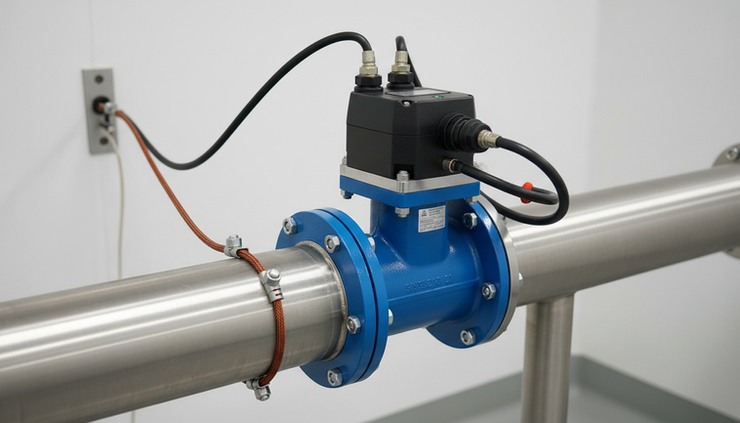
Understand what each device does
An electromagnetic flow meter, often called a mag meter, measures the flow of conductive liquid through a pipe. It uses Faraday’s law of electromagnetic induction. As the liquid moves through a magnetic field, it generates a small voltage that relates to flow velocity.
The ProSight Meter acts as the display, monitoring, or receiving device. Depending on the setup, it may read one of several signal types from the flow meter:
4 to 20 mA analogue signal
Pulse or frequency output
Digital communication, such as Modbus or another supported protocol
Alarm or status contacts
Most industrial installations use 4 to 20 mA because it is simple, reliable, and easy to test with a multimeter. Pulse output is common when totalised flow is needed. Digital communication can provide more data, but it must be configured carefully.
Before wiring anything, confirm three details:
The flow meter output type.
The ProSight Meter input type.
The power requirements for both devices.
If these do not match, the connection will not work even if the wiring looks neat.
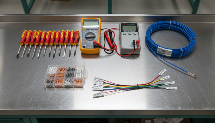
Gather the tools and equipment
Good preparation prevents most connection problems. A loose shield, wrong cable type, or missing ferrule can cause unstable readings that are hard to trace later.
Item | Purpose |
Flow meter manual | Confirms terminal labels, output type, power, and grounding needs |
ProSight Meter manual | Confirms input terminals, scaling menu, and communication settings |
Multimeter | Checks voltage, continuity, loop current, and resistance |
Loop calibrator | Simulates or measures 4 to 20 mA signals |
Insulated screwdrivers | Tightens terminals safely |
Wire strippers and cutters | Prepares cable ends cleanly |
Ferrules and crimp tool | Gives stranded wire a reliable terminal connection |
Screened twisted pair cable | Helps protect low-level signals from electrical noise |
Earth bonding cable | Supports correct grounding and noise control |
Cable glands and seals | Keeps enclosures protected from moisture and dust |
Labels or heat-shrink markers | Makes future maintenance easier |
For outdoor or washdown areas, check the enclosure rating and cable gland rating. A well-wired meter can still fail if moisture enters the terminal box.
Check the installation before connecting wires
Electrical connection is only one part of the job. The meter also needs the right pipe conditions.
Check these points before you start wiring:
The pipe is full during operation.
The flow direction matches the arrow on the meter body.
The meter has suitable straight pipe lengths if the manufacturer requires them.
The liquid is conductive enough for an electromagnetic meter.
The sensor is not installed at the highest point of a pipe where air can collect.
The meter body and pipework are correctly bonded or grounded.
The cable route avoids high-voltage cables, variable speed drives, and motors where possible.
Grounding matters more with mag meters than many beginners expect. The measurement signal is small, so poor bonding can create noise, zero drift, or unstable readings. On non-metallic or lined pipes, grounding rings or grounding electrodes may be needed. Follow the flow meter manufacturer’s method.
Connect the flow meter to the ProSight Meter step by step
The steps below describe a common installation. Treat them as a working sequence, not a replacement for the wiring diagrams supplied with your devices.
1. Isolate power and make the area safe
Turn off power to the ProSight Meter and the electromagnetic flow meter. Lock out and tag out the circuit if required by your site procedure.
Use a multimeter to confirm the terminals are de-energised before touching them. Do not rely only on a switch position or indicator light.
2. Confirm the output and input match
Open the terminal covers and compare the labels with the manuals.
For a 4 to 20 mA connection, look for terminals such as:
`mA+` and `mA-` on the flow meter
`AI+` and `AI-` on the ProSight Meter
Possibly `24 V+` and `0 V` if the loop is externally powered
For a pulse output, look for labels such as:
`Pulse+` and `Pulse-`
`DO+` and `DO-`
`Open collector`
`Frequency output`
For digital communication, look for terminals such as:
`A` and `B`
`D+` and `D-`
`RS485+` and `RS485-`
Do not assume labels are universal. One manufacturer’s `A` terminal may be another manufacturer’s `B`. If communication fails later, polarity is one of the first things to check.
3. Select the correct cable
Use screened twisted pair cable for analogue and pulse signals. Keep signal cables separate from mains power cables. If the signal cable must cross a power cable, cross it at right angles rather than running it beside the cable.
For RS485 or similar digital communication, use the cable type recommended by the manufacturer. Impedance, shielding, and termination can affect reliability over longer runs.
4. Prepare and label each conductor
Cut the cable to length with enough spare for service loops, but avoid large coils inside the enclosure. Strip the outer sheath carefully so you do not nick the conductor insulation.
Fit ferrules to stranded conductors. Label each wire before landing it. Labels such as `Flow mA+`, `Flow mA-`, `Shield`, and `0 V` can save a lot of time during commissioning.
5. Wire the 4 to 20 mA signal if using analogue input
For a typical analogue loop, connect the flow meter’s current output to the ProSight Meter’s analogue input. The exact wiring depends on whether the loop is powered by the flow meter, the ProSight Meter, or an external 24 V DC supply.
A common externally powered loop follows this path:
24 V DC positive to the flow meter current output positive.
Flow meter current output negative to ProSight Meter analogue input positive.
ProSight Meter analogue input negative to 24 V DC negative.
Some devices have active outputs and do not need loop power in the same way. Others have passive outputs and require an external supply. Check this carefully. Connecting an active output to an active input can give wrong readings or damage equipment.
6. Wire the pulse output if total flow is required
If the installation uses pulse output, connect the pulse terminals from the flow meter to the pulse or digital input on the ProSight Meter.
Open collector outputs often need a pull-up resistor or a powered input. Some meters provide a dry contact or transistor output. The ProSight Meter input type must suit the flow meter output.
Set the pulse value later during configuration. For example, the meter may be configured so one pulse equals a set volume. Use the same unit basis across both devices.
7. Wire the communication terminals if using digital data
For RS485-style communication, connect the positive and negative data lines according to the manuals. If the line is part of a longer network, check termination resistors and device addressing.
Keep the shield continuous where possible, but connect it according to site earthing practice and manufacturer advice. In many systems, the shield is grounded at one end to reduce ground loop issues.
8. Connect shields and grounding correctly
Terminate cable shields neatly. Do not leave long shield tails floating inside the enclosure. They can act like antennas.
Bond the flow meter body to the pipework or plant earth as required. If grounding rings are installed, check that they are connected firmly.
For analogue signal cables, avoid using the shield as a signal return. The shield protects the signal. It should not carry normal operating current unless the manufacturer has designed it that way.
9. Tighten, inspect, and close the enclosures
Tug each conductor lightly to confirm it is secure. Check that no copper strands are exposed outside the terminals. Confirm cable glands are tight and seals are seated properly.
Before applying power, compare every wire against the wiring diagram. This is the best moment to find a mistake.
10. Power up and check the live signal
Turn on power and watch for fault messages on both devices. If the flow meter has a local display, compare it with the ProSight Meter display.
For a 4 to 20 mA loop, measure the loop current with a multimeter or loop calibrator. At zero flow, many meters output 4 mA, though some may suppress low flow or show a configured value. At higher flow, the signal should rise smoothly.
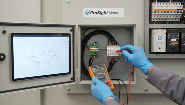
Configure the ProSight Meter
Once the wiring is correct, set up the ProSight Meter so it understands the signal.
For an analogue input, configure:
Input type as `4-20 mA`
Low range value, such as zero flow
High range value, based on the flow meter’s full-scale output
Units, such as L/min, m³/h, or kL/day
Decimal places
Damping or filtering if readings fluctuate
Alarm setpoints if required
For pulse input, configure:
Pulse input type
Pulse value
Totaliser units
Debounce or filtering if available
Reset behaviour for totals
For digital communication, configure:
Device address
Baud rate
Parity
Stop bits
Register mapping
Data format
The flow meter and ProSight Meter must use the same scaling. If the flow meter sends 20 mA at 100 m³/h, but the ProSight Meter is set to 20 mA at 150 m³/h, the display will be wrong even though the loop current is correct.
Calibrate and verify the measurement
Calibration proves that the system reads correctly across the working range. There are two parts to think about: the flow meter calibration and the ProSight Meter input calibration.
The flow meter itself is normally factory calibrated. In many cases, you do not adjust the sensor unless a qualified technician performs a formal calibration. The ProSight Meter needs to be scaled and verified to match the flow meter output.
A practical verification process looks like this:
Use a loop calibrator to inject 4 mA into the ProSight Meter input.
Confirm the display shows the low range value.
Inject 12 mA and confirm the display shows the midpoint.
Inject 20 mA and confirm the display shows the high range value.
Reconnect the flow meter.
Compare the ProSight reading with the flow meter display or a known process condition.
For higher accuracy, use a known flow reference or a calibrated test rig. For plant checks, compare against tank drawdown, batch volume, or another trusted instrument if available.
Record the results with the date, range, units, test equipment used, and any adjustments made. Good records make drift and recurring faults easier to spot.
Common challenges and how to fix them
Connection faults often look like process problems at first. Work through them methodically.
Symptom | Likely cause | What to check |
ProSight Meter shows zero all the time | Open loop, no power, wrong input type | Check 24 V DC, loop continuity, input setting |
Reading is stuck high | Reversed wiring, active input conflict, fault current | Check polarity and active/passive output type |
Reading jumps around | Poor grounding, electrical noise, air in pipe | Check shield, earth bonding, cable route, pipe condition |
Reading is offset | Scaling mismatch or zero setting issue | Compare 4 mA and 20 mA range settings |
Pulse total is wrong | Incorrect pulse value | Match pulse volume on both devices |
Digital communication fails | Address or baud mismatch | Check address, baud rate, parity, A/B polarity |
Fault appears in wet weather | Moisture ingress | Inspect glands, seals, enclosure rating |
If the reading is unstable, do not start by changing damping. Damping can hide noise, but it does not fix the cause. Check grounding, shielding, cable routing, and pipe fill first.
If the signal reads backwards or total flow subtracts, check flow direction settings. Some flow meters can detect reverse flow, and the ProSight Meter may need settings for signed flow or direction handling.
Maintain the system for best performance
A connected flow system needs periodic checks, especially in harsh sites or outdoor installations. Build these tasks into the maintenance schedule.
Inspect wiring and enclosures
Look for cracked glands, loose terminals, corrosion, water marks, and damaged cable sheaths. Tighten terminals only to the manufacturer’s recommended torque if specified. Over-tightening can damage terminal blocks.
Check grounding and shielding
Ground connections can loosen or corrode over time. Confirm bonding straps are intact and shield terminations are secure. This is especially useful after pipework changes or nearby electrical work.
Review zero flow behaviour
When the pipe is full and flow is stopped, the reading should be stable near zero. If it drifts, check for air pockets, empty pipe conditions, grounding issues, or sensor contamination.
Clean only when needed
Electromagnetic meters have no moving parts, which reduces maintenance. Still, coatings or deposits on electrodes can affect readings. Cleaning depends on the liquid and sensor design. Use approved cleaning methods only, especially for lined meters.
Keep configuration records
Save or write down the ProSight Meter settings, including scaling, units, alarms, pulse values, and communication settings. If a unit is replaced, these records help restore service quickly.
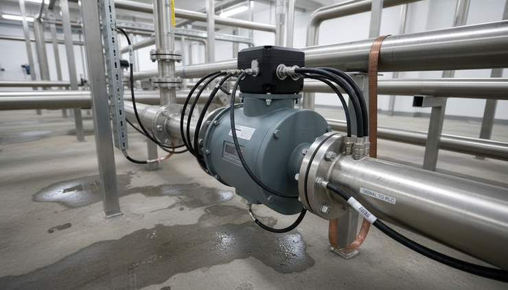
What a successful connection looks like
A correct installation is easy to recognise. The ProSight Meter powers up without faults, the displayed units match the process, and the reading changes smoothly as flow changes. A 4 to 20 mA test gives the expected low, middle, and high values. Pulse totals increase at the right rate. Digital communication stays stable without dropouts.
The best results come from treating wiring, grounding, configuration, and calibration as one system. Do not rush the final checks. A few extra minutes with a multimeter and the manuals can prevent hours of fault-finding later.
When the meter is wired cleanly, scaled correctly, and maintained on a regular schedule, the ProSight Meter becomes a dependable window into the process. That is the goal: a flow reading you can trust when operations, reporting, or control decisions depend on it.


