.png)
FieldLink Wireless Pump and Tank Control for Remote Sites Without Internet
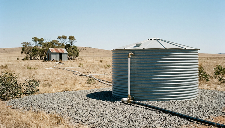
A tank on a ridge and a pump down in a valley can be only a few kilometres apart, but control-wise they may as well be on different sites if there is no internet, no cable route, and no reliable mobile coverage. The pump needs to know when the tank is low. The tank needs protection from overflow. The pump also needs protection from dry running, pressure faults, and unwanted restarts.
That is where a correctly specified FieldLink™ wireless control system can fit. It can link level signals at the tank to pump start and stop outputs at the pump station, without relying on cloud services or a public network. The key is to treat the radio link as one part of the control system, not as the whole solution.
A good design starts with the process. How much water does the tank hold? How quickly does it fill? What happens if communications fail? What local controls are needed if an operator is standing at the pump? Those answers shape the inputs, outputs, radio path, and fail-safe behaviour.
Start with the control duty before choosing equipment
Wireless pump and tank control sounds simple. Tank low starts pump. Tank full stops pump. In the field, the control duty usually needs more detail.
The first design step is to define the normal operating sequence:
When should the pump start?
When should it stop?
Is there one pump or a duty and standby pair?
Does the tank fill directly, or through valves and pipework with delay?
Can the pump run continuously, or does it have a maximum run time?
What happens after a power failure?
Who is allowed to run the pump locally?
These questions decide how many signals the FieldLink system must carry between sites. They also decide what still needs to happen in hardwired local control at each end.
For a basic arrangement, the tank site may send a low-level demand signal to the pump site. The pump site may return a pump running or fault signal. More involved sites may need high-level alarms, low-low cut-outs, pressure switch status, flow switch status, door alarms, generator status, or selector switch positions.
The best approach is to draw a simple cause-and-effect table before hardware selection. Each input should have a clear result. Each output should have a defined safe state. This prevents a common problem where the wireless link works perfectly, but the process logic still leaves the tank or pump exposed.
The radio link can carry the command, but the control design decides whether the site behaves safely when something goes wrong.
Level inputs need clear set points and the right sensor type
The tank level is usually the main signal for pump control. The sensor choice depends on the tank, the accuracy needed, the environment, and how much local indication is required.
Common level input options include:
Level input type | Where it fits | Design notes |
Float switches | Simple start, stop, and alarm points | Easy to understand, but each point needs its own switch and wiring |
Conductivity probes | Suitable for conductive water in some tanks | Water quality and probe maintenance matter |
Pressure transducers | Continuous level from tank head pressure | Needs scaling, surge protection, and correct mounting |
Ultrasonic level sensors | Non-contact measurement from tank roof | Can be affected by foam, condensation, internal beams, or turbulence |
Radar level sensors | Non-contact measurement in tougher conditions | Higher cost, but often better around vapour or condensation |
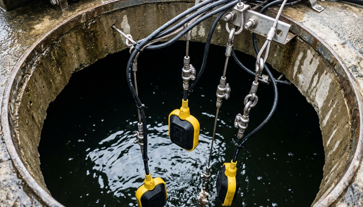
For start and stop control, discrete float switches can be enough. A low-level float asks the pump to start. A high-level float asks it to stop. A separate high-high float can provide an independent overflow alarm or pump inhibit. A low-low float in the tank can signal abnormal depletion.
For better visibility, an analogue level transmitter can send a continuous level. The control system can then create start, stop, low alarm, and high alarm set points in logic. This approach is useful where operators need a percentage level, trend, or tighter control band.
The control band matters. If the difference between start and stop is too narrow, the pump may short-cycle. If the band is too wide, the tank may fall too low before refill. Pipe length, pump capacity, peak demand, and tank volume all affect the right settings.
Good level design also allows for maintenance. A stuck float, blocked stilling tube, failed sensor, or damaged cable should not create an uncontrolled fill. Where overflow has serious consequences, use independent high-level protection, not only the same level device that starts and stops the pump.
Control outputs must match the pump starter and local controls
At the pump end, the wireless signal usually drives a control output rather than the pump motor directly. That output may connect to a motor starter, variable speed drive, PLC input, relay panel, or pump controller.
The output design should answer four questions.
What starts the pump?
The FieldLink receiver may close a relay contact into the pump control circuit. That contact could represent remote demand from the tank. The local starter still handles motor protection, overloads, interlocks, and emergency stop circuits.
What stops the pump?
The pump may stop when the tank reaches high level, when a maximum run timer expires, when suction pressure falls, when a fault occurs, or when an operator selects local stop. Stop logic should not rely on just one path if the outcome matters.
What confirms that the pump has run?
A feedback input from the pump end can report pump run status, starter fault, VSD fault, or no-flow alarm back to the tank or to a local indicator panel. Even where no operator views the signal remotely, feedback helps with diagnostics on site.
What happens after faults clear?
Automatic restart can be useful on unattended water systems, but it can also hide repeat faults. Dry-run trips, overloads, and pressure faults need reset logic that suits the site. Some faults should latch until inspected. Others may allow limited restart attempts.
For a single pump, control may use one remote start output and a few status inputs. For duty and standby pumps, the logic may need alternation, failed-to-start detection, and a way to bring on the second pump. If that logic already exists in a local pump controller, the wireless system may only need to provide tank demand and receive common fault status.
The safest designs keep critical motor protection hardwired and local. Wireless commands can request operation, but overload protection, emergency stops, dry-run cut-outs, and dangerous pressure protection should not depend only on radio communication.
The radio path determines whether the link is practical
A FieldLink wireless pump and tank control project should include a radio-path assessment before the system is finalised. Distance alone does not decide whether the link will work. The path between antennas matters more.
A clear line of sight is ideal. In many rural and regional Australian sites, the tank may be on high ground, which helps. Problems start when the path crosses ridges, dense trees, metal structures, sheds, or earth banks. Seasonal growth can also change the path. A link that works in dry months may weaken when trees leaf up or when wet foliage absorbs signal.
A practical assessment should look at:
Antenna height at both ends
Terrain between the tank and pump
Nearby metalwork and electrical noise sources
Cable losses between radio and antenna
Power availability at the remote end
Enclosure location and weather exposure
Required signal range and response time
Any requirements for licensed or licence-exempt radio equipment
A site sketch is useful, but it does not replace field checks. On difficult paths, a temporary test can confirm signal strength and reliability before permanent installation. If the path is blocked, raising an antenna, shifting a cabinet, or using a repeater location may solve the problem.
Power supply design also sits beside the radio assessment. Some tank sites have mains power. Others may need solar and battery supply. The duty cycle of the radio, connected sensors, and any local indicators affects panel sizing. Surge protection and earthing deserve attention, especially where antennas and long cable runs are exposed to storms.
Local operating modes keep the site usable
Remote control should not make the site hard to operate when someone is physically there. Local operating modes give operators, electricians, and maintenance crews a safe way to test and run equipment.
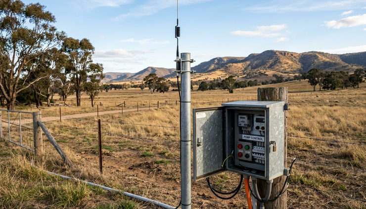
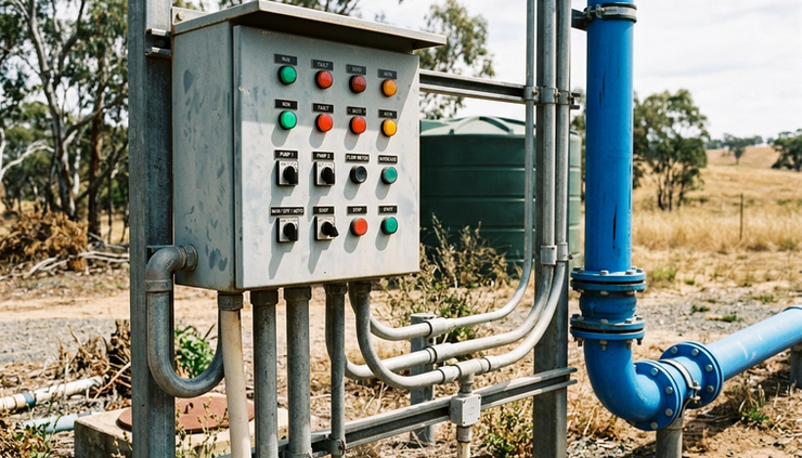
A typical pump control panel may include a `Local / Off / Remote` selector.
In `Remote`, the pump responds to the tank demand signal carried by the FieldLink system, subject to all local interlocks.
In `Off`, the pump is stopped and cannot start from remote demand. This mode is useful during maintenance, but it must be clear at the tank or control point that the pump is unavailable.
In `Local`, an authorised person can run the pump from the pump station. Even then, dry-run protection, overloads, and emergency stop circuits should remain active. Local mode should not bypass essential protection unless a formal maintenance procedure controls the risk.
The tank end may also need local controls. For example, a tank-side panel may show radio link health, pump running status, high-level alarm, and low-level alarm. If there is a valve or local booster pump at the tank, those functions need their own safe modes too.
Clear indication prevents confusion. If the pump is not responding to a low-tank condition, an operator should be able to tell whether the cause is:
No demand from the level system
Pump panel in `Off` or `Local`
Radio link fault
Pump fault
Dry-run protection active
Power supply fault
High-level inhibit active
Labels and simple lamps can save hours of fault-finding. They also reduce the temptation to bypass protection to “get water moving”.
Communication-loss behaviour must be designed, not assumed
Every wireless control project must define what happens when the radio link drops out. The wrong answer can empty a source tank, dead-head a pump, or overflow a receiving tank.
There is no single safe state for all systems. For some sites, loss of signal should stop the pump. For others, a short hold-last-state period may be acceptable before shutdown. A stock water system, irrigation header tank, fire service reserve, or potable water storage may each need different behaviour.
The design should specify:
Timeout period
How long can the system tolerate no valid signal before action is taken? A few seconds may be right for some processes. Other water transfer systems can tolerate a longer delay.
Output state on timeout
Should the pump demand output turn off, stay on briefly, or move to another defined state? This must be deliberate.
Alarm indication
A communication-loss alarm should appear locally. If the site has telemetry by another path, it may also report there. Where there is no internet, the local indication becomes even more important.
Recovery behaviour
When the link returns, should the pump resume automatically if the tank is low? Should there be a delay? Should an alarm latch until acknowledged?
For most tank filling duties, a communications fault should not create an overflow risk. That often means the pump should stop after a defined loss of valid tank signal. The exact arrangement still needs to allow for water demand, tank reserve, and operational requirements.
Dry-run protection belongs at the pump
Dry running can damage pumps, seals, and pipework. It can also create heat and poor water quality outcomes in some systems. Because dry-run risk sits at the pump and suction source, protection should be local to the pump station.
Common dry-run protection methods include:
Suction pressure switch or pressure transmitter
Bore level probe or low-level switch
Flow switch or no-flow detection
Pump power monitoring
VSD protection functions
Minimum pressure logic after start-up
The protection method should suit the source. A bore pump, dam suction pump, break tank transfer pump, and mains-boosted system each behave differently.
Dry-run protection should normally stop the pump even if the remote tank is calling for water. The remote demand is only a request. It should not override pump safety.
Reset logic also needs thought. An automatic reset after a short delay can help where suction recovers naturally. Repeated automatic restarts can be harmful if the source remains dry. A common approach is to allow limited restart attempts, then latch a fault for inspection. The right choice depends on the site and the cost of a missed water transfer compared with the cost of pump damage.
Overflow prevention needs more than one layer
Overflow prevention starts with a sensible stop level, but it should not end there. A failed level sensor, welded relay, software error, or manual override can all defeat the normal stop command.
Good overflow prevention may include:
A normal high-level stop command
An independent high-high level switch
A hardwired pump inhibit from the high-high switch where practical
A local overflow alarm lamp or siren
A mechanical overflow pipe or drainage path sized for the duty
A maximum pump run timer
Regular testing of level devices
The mechanical overflow path is easy to overlook. Controls reduce the chance of overflow, but tanks should still have a safe place for excess water to go if something fails. This is especially important near buildings, roads, electrical equipment, containment areas, or erosion-prone ground.
A high-high level switch should be mounted and wired so it provides real independence from the normal level input where the risk requires it. Using the same sensor, same scaling, and same logic for normal stop and emergency overflow protection can leave one fault able to defeat both.
A complete FieldLink specification ties the pieces together
A useful specification does more than list a transmitter and receiver. It describes the process, the signals, the radio path, and the required behaviour under normal and abnormal conditions.
For a remote tank and pump project, the specification should cover:
Tank level devices and set points
Pump start and stop logic
Input and output count at each site
Status feedback and alarm signals
Local selector switches and indication
Dry-run and motor protection
Overflow prevention layers
Communication-loss timeout and output state
Power supply, solar supply if needed, and battery hold-up
Antenna type, mounting height, cable route, and earthing
Enclosure rating and environmental conditions
Testing, commissioning, and handover checks
Commissioning should prove the full sequence, not only the radio signal. Test low-level start, high-level stop, high-high inhibit, dry-run trip, pump fault, local mode, off mode, power failure recovery, and radio loss. Record the set points and timeout values so future maintenance does not rely on guesswork.
FieldLink wireless pump and tank control can be a practical way to automate remote water transfer where internet access is limited or unavailable. The system works best when the wireless link is specified around the site’s real control needs. Level inputs, control outputs, radio-path checks, and local operating modes all matter.
The main takeaway is simple: design the failure behaviour before the first cabinet is installed. If communication-loss action, dry-run protection, and overflow prevention are built into the complete control arrangement, the site is far more likely to keep moving water safely when conditions are less than ideal.


