Troubleshooting Guide for Inverter Issues After Wiring Installation
- 3 minutes ago
- 3 min read
When an inverter, or variable frequency drive (VFD), fails to work after wiring, it can cause frustration and downtime. Understanding how to methodically troubleshoot the problem helps save time and prevents damage to equipment. This guide walks through practical steps to identify and fix common issues that prevent an inverter from operating correctly after installation.

Check Power Connections
Start by confirming the power supply to the inverter is correct. The inverter requires a stable voltage within its rated range to function properly.
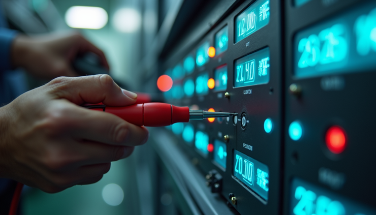
Use a multimeter to measure the input voltage at the inverter terminals.
Verify the supply voltage matches the inverter’s specifications (e.g., 220V, 380V).
Check that the power input connections follow the correct phase sequence and polarity.
Ensure circuit breakers or fuses feeding the inverter are not tripped or blown.
Incorrect or unstable power supply is a common cause of inverter failure after wiring. Fixing power issues early prevents further damage.
Inspect Wiring Thoroughly
Next, examine all wiring connections carefully.
Confirm that all wires are securely fastened and no terminals are loose.
Check that the main power circuit wiring matches the inverter’s input and output terminals (e.g., RST to UVW or L1/L2/L3 to M1/M2/M3).
Verify control circuit wiring, including start/stop signals and speed control inputs, is correct.
Look for any signs of damaged insulation, broken wires, or incorrect wire gauge.
Loose or incorrect wiring can prevent the inverter from powering on or cause erratic behavior.
Perform Static Testing on Internal Components
Use a multimeter to test the inverter’s internal components without powering it on.
Measure resistance across the inverter’s IGBTs or transistors to check for shorts or open circuits.
Test the DC bus capacitor for proper charging by measuring voltage buildup after applying power briefly.
If any component shows abnormal resistance or no charge, it may be faulty and require replacement.
Static testing helps identify hardware faults that wiring checks alone cannot reveal.
Verify Control Signals and Panel Settings
The inverter relies on external control signals to operate.
Confirm that start, stop, and speed control signals are connected and functioning.
If using a control panel, check that settings such as run mode, frequency limits, and acceleration time are configured correctly.
Test control inputs with a multimeter or signal generator to ensure the inverter receives commands.
Incorrect or missing control signals often cause the inverter to remain inactive.
Review Parameter Settings for Motor Compatibility
The inverter’s parameters must match the connected motor’s specifications.
Check rated motor power, voltage, current, and speed settings in the inverter parameters.
Ensure the frequency range is set within the motor’s limits.
Confirm startup mode and acceleration/deceleration times suit the application.
Mismatched parameters can prevent the motor from starting or cause protective shutdowns.
Conduct a No-load Test
Before connecting the motor, run the inverter without load to observe output behavior.
Start the inverter and measure the output voltages on U, V, and W terminals.
Check that the three-phase output voltages are balanced and within expected ranges.
Listen for unusual noises or vibrations from the inverter.
A successful no-load test indicates the inverter hardware and wiring are likely sound.
Perform a Load Test with the Motor
Connect the motor and test the inverter under load conditions.
Start the motor via the inverter and observe if it runs smoothly.
Check the motor rotation direction; reverse two output wires if the direction is incorrect.
Monitor current draw and temperature to ensure they stay within safe limits.
A motor that fails to start or runs abnormally signals wiring, parameter, or motor issues.
Inspect the Motor and Load Conditions
Sometimes the problem lies with the motor or the mechanical load.
Measure the motor’s insulation resistance and winding resistance to detect faults.
Confirm the load does not exceed the motor or inverter capacity.
Look for mechanical obstructions or binding in the load.
A faulty motor or excessive load can cause the inverter to trip or fail to start.
Check for Fault Codes and Alarms
Most modern inverters display fault codes when problems occur.
Observe the inverter’s display panel for error messages.
Refer to the inverter’s manual to interpret fault codes.
Address the specific faults indicated, such as overcurrent, overvoltage, or communication errors.
Fault codes provide valuable clues to pinpoint the root cause quickly.
Dealing with an inverter that does not work after wiring requires a systematic approach. Start with power and wiring checks, then move to control signals and parameter settings. Testing without load and under load helps isolate hardware or motor issues. Always consult the inverter manual for specific fault codes and troubleshooting tips.
By following these steps carefully, you can identify and fix most inverter problems after installation, reducing downtime and protecting your equipment. If issues persist, consider consulting a qualified technician for advanced diagnostics.


