.png)
How to Scope a Small Industrial Automation Project for Signals Sequences HMI and Testing
Small automation projects often fail for simple reasons. A sensor was assumed but not specified. A sequence step lived only in someone’s head. An HMI screen showed the right data, but in the wrong order for the operator. A test passed in the workshop, then failed beside a hot washdown area on site.
Good scoping stops these problems early. It turns a rough idea, such as “automate this transfer station”, into a clear set of signals, sequences, screens, outputs, site limits, and acceptance tests. The scope does not need to be a 100-page document. It does need to be specific enough that an electrician, controls programmer, mechanical fitter, operator, and project owner can all work from the same picture.
This guide walks through a practical way to scope a small industrial automation project, using plain examples from typical machinery, conveyors, pumps, valves, and small process systems.

Start by naming every signal and why it matters
Signals are the control system’s view of the real world. If the signal list is weak, the rest of the project becomes guesswork.
A signal can be an input or output. Inputs tell the controller what is happening. Outputs tell the machine what to do. For scoping, start with inputs because they define what the system can know.
Common input signals include:
Proximity switches for cylinder end positions
Photoelectric sensors for product detection
Pressure switches for compressed air or hydraulic pressure
Flow switches for pump confirmation
Analogue transmitters for temperature, level, pressure, or weight
Emergency stop channels and safety gate feedback
Pushbuttons, selector switches, and reset buttons
Do not stop at the signal name. For each signal, record what it means and how it should behave. “Product sensor” is vague. “Infeed product present, blocked when carton covers the photoeye for at least 200 ms” is useful.
A simple signal table helps remove doubt.
Signal name | Type | Normal meaning | Fault meaning | Scope note |
Infeed photoeye | Digital input | Product is ready to enter | Stuck on or blocked too long | Needs mounting bracket and reflector |
Air pressure OK | Digital input | Machine has enough air to run | Low air, stop cycle safely | Confirm setpoint with pneumatics supplier |
Tank level | Analogue input | Current fill level | Out of range or noisy reading | Define engineering units and scaling |
Guard closed | Safety input | Access door is shut | Door open or safety fault | Must be part of safety circuit design |
For analogue signals, include the range and units. A pressure transmitter might be 4 to 20 mA, scaled from 0 to 1,000 kPa. A temperature sensor might use a 0 to 10 V signal or a resistance temperature device connected through a module. The controller, electrical design, and HMI all need the same scaling.
For digital signals, define the normal state. Is the sensor normally on when healthy, or normally off? Does the input fail safe if a cable breaks? For safety-related signals, involve a competent safety designer and follow relevant site and Australian requirements. Do not treat safety inputs as ordinary machine inputs.
A good signal scope answers these questions:
What physical item creates the signal?
Where is it mounted?
What controller input receives it?
What does on, off, high, low, or out of range mean?
What should the machine do if the signal is missing, stuck, or inconsistent?
That last question is where many small projects improve quickly. A machine that only works when everything is perfect is easy to program. A machine that fails clearly and safely is better scoped.
Define the sequence before writing any code
A sequence is the order of actions the machine follows. It is the story of the process. For a small automation job, this can be a written step list, a flow chart, or a state table. The format matters less than the clarity.
Take a simple transfer station with a pneumatic pusher. A loose description might say:
“The product comes in, then the pusher moves it across and returns.”
That is not enough to build or test. A scoped sequence should look more like this:
Wait for machine ready, air pressure OK, guard closed, and no active faults.
Wait for the infeed sensor to detect product.
Start the infeed conveyor.
Stop the conveyor when product reaches the transfer position sensor.
Check the pusher is retracted.
Extend the pusher.
Confirm extended position within the allowed time.
Retract the pusher.
Confirm retracted position within the allowed time.
10. Release the outfeed conveyor or signal downstream ready.
11. Return to waiting for the next product.
Each step needs entry conditions, actions, and exit conditions.
Sequence item | What to define | Example |
Entry condition | What must be true before the step starts | Product at transfer position and pusher retracted |
Action | What the controller turns on or commands | Energise pusher extend valve |
Exit condition | What proves the step is complete | Extended sensor turns on |
Timeout | How long the system waits before faulting | Fault if not extended within 2 seconds |
Fault response | What happens when the step fails | De-energise valve and show pusher extend fault |
Timeouts deserve special attention. They turn silent failures into diagnosable faults. If a cylinder does not extend, the HMI should not just say “Machine fault”. It should say something like `Pusher failed to extend`. That points maintenance towards air pressure, valve operation, cylinder binding, sensor position, or wiring.
Separate automatic, manual, and maintenance modes early in the scope. Operators often need automatic start, stop, reset, and clear fault functions. Maintenance staff may need manual jog controls for conveyors, valves, or cylinders. Define which actions are allowed in each mode and what interlocks still apply.
A clear sequence also reduces scope creep. If someone asks for a new function later, it becomes obvious where it fits, what signals it needs, and what tests must change.

Design HMI screens around the operator’s work
A good HMI does not show everything. It shows the right thing at the right time.
For a small project, the HMI often has only a few screens. That makes scoping even more important because every button, alarm, and display must earn its place. Start by listing what the operator needs to do during a normal shift.
Common operator tasks include:
Start and stop the machine
See whether the machine is ready
Understand why it will not start
Change simple setpoints
Clear faults after fixing the cause
Run manual movements during setup
View counts, cycle status, or batch progress
The main screen should answer three questions quickly:
Is the machine running, stopped, faulted, or waiting?
What step is active now?
What does the operator need to do next?
Avoid filling the main screen with raw input names unless the operator uses them. A technician might care that `I:2/07` is on. An operator needs “Product at transfer position” or “Waiting for carton”.
A useful small-machine HMI structure might include:
Screen | Purpose | Typical content |
Home | Run the machine and see status | Start, stop, reset, current step, key permissives |
Alarms | Show active and past faults | Time, fault text, likely check points |
Manual | Move items during setup or maintenance | Jog buttons, position feedback, mode warnings |
Settings | Adjust approved values | Timers, counts, speed setpoints, access control |
I/O status | Support fault finding | Inputs, outputs, analogue values, simulation status if used |
Use plain fault text. “Fault 37” wastes time unless everyone has the manual open. “Outfeed conveyor not ready” helps straight away. If a fault has a common cause, include a short prompt such as “Check downstream ready signal”.
HMI scoping should also cover access levels. Not every user should be able to change a fill target, bypass a sensor, or run a manual movement. Define which settings are operator-level, supervisor-level, or maintenance-level. Keep this simple, but make it deliberate.
For Australian sites, also think about labels and units. Use local spelling, familiar terms, and site-standard units. If production records use litres, do not show cubic metres unless there is a reason. If pressure is maintained in kPa across the site, keep the HMI consistent.
Identify outputs and specify what they must drive
Outputs are where the control system acts on the machine. A scope should name each output, but it should also describe the device being driven. This prevents undersized outputs, missing interposing relays, and late changes to the electrical design.
Common outputs include:
Motor contactors and variable speed drive run commands
Solenoid valves for pneumatic or hydraulic cylinders
Stack lights and sounders
Pump start commands
Heater enable signals
Brake release commands
Reject gates or diverter actuators
Signals to upstream or downstream equipment
For each output, define the electrical and functional details.
Output | Device driven | Electrical detail | Functional note |
Infeed conveyor run | Motor starter or drive input | 24 V DC command or relay contact | Runs only in auto when downstream is ready |
Pusher extend | Solenoid valve coil | Confirm voltage and current draw | Must de-energise on stop or fault |
Amber beacon | Stack light | 24 V DC output | On when machine is waiting for operator |
Pump start | Contactor coil or drive input | Confirm interface type | Interlocked with low-level protection |
Voltage matters. Current draw matters. Whether the output drives a coil directly or through a relay matters. If the load is inductive, the electrical design should include suitable suppression. If the output controls a drive, define whether the system uses hardwired inputs, fieldbus, analogue speed reference, or a combination.
Also specify the required state on stop, emergency stop, power loss, and fault. For example, a spring-return valve might be a good choice if a cylinder must retract when power drops. By contrast, a double-solenoid valve may hold its last position, which can be right or wrong depending on the hazard and process.
Outputs also need names that match the sequence. If the sequence says “open fill valve”, do not call the output “Solenoid 4” in all documents. Device tags can exist, but the functional name keeps commissioning sane.
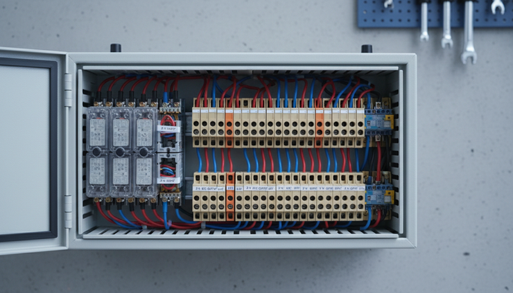
Check the environment before choosing parts
The surrounding environment can change the whole scope. A sensor that works well in a dry workshop may fail beside steam, dust, vibration, washdown water, or direct sun. A control panel that is fine indoors may be unsuitable near corrosive vapour or high ambient heat.
Record the site conditions early. Walk the area if possible. If not, ask for photos, layout drawings, and details from maintenance staff.
Key environmental factors include:
Temperature range near the equipment
Dust, powder, oil mist, water spray, or washdown
Vibration from nearby machinery
Chemical exposure
Sunlight on sensors or HMI screens
Electrical noise from welders, drives, or large motors
Cable run lengths and routing limits
Available power, air, water, and network points
Access for cleaning, servicing, and emergency response
These details affect component choices. A photoeye may need background suppression, a stainless bracket, or a protective guard. A panel may need a higher ingress protection rating, ventilation, or cooling. An HMI may need a screen that remains readable in bright areas. Cables may need mechanical protection or different jacket materials.
Do not assume “factory floor” means one condition. A food processing room, timber mill, metal fabrication bay, quarry plant, and packaging line can all need very different hardware.
Environmental scoping should also include human access. Can an operator reach the HMI without leaning over moving equipment? Can maintenance staff see an actuator while jogging it? Can a sensor be adjusted without removing half the guarding? These questions shape brackets, cable routes, screen location, and manual controls.
Build acceptance testing into the scope
Acceptance testing proves the project meets the agreed scope. It should not be left until the last day, when everyone is tired and production is waiting.
For small projects, use two stages where practical.
Factory acceptance testing happens before delivery or installation, often in a workshop. Site acceptance testing happens after installation, with real services, real product, and site operators.
A practical acceptance test plan should cover:
Review the documentation
Check the signal list, output list, sequence, HMI screens, drawings, and test sheets match the agreed scope.
Check the I/O point by point
Turn each input on and off safely, then confirm the controller and HMI show the correct state. Force nothing unless the test method allows it and the risks are controlled.
Test each output safely
Verify the correct device operates. Confirm the safe state on stop, fault, and power cycle where suitable.
Run the automatic sequence
Step through normal operation. Confirm each timeout, interlock, and transition works as written.
Test faults and recovery
Simulate common faults, such as missing product, low air pressure, blocked photoeye, actuator timeout, or downstream not ready. Confirm the alarm text is clear and reset only works after the cause is fixed.
Check manual mode
Confirm jog controls work only under the agreed conditions. Make sure position feedback, warnings, and interlocks behave as scoped.
Confirm HMI usability
Ask an operator or maintainer to start, stop, fault-find, and reset the machine using only the screen and normal site instructions.
Record results and defects
Mark each test as pass, fail, or not tested. Assign every defect to someone and retest after correction.
Use real acceptance criteria. “Works correctly” is weak. “When the infeed photoeye is blocked for more than 10 seconds while the conveyor is stopped, the HMI shows ‘Infeed sensor blocked’ and automatic start is prevented” is testable.
If a function is too vague to test, it is too vague to scope.
Acceptance testing also protects relationships. It gives the project owner, builder, programmer, and site team a shared way to decide whether the job is finished.

Use a simple scoping checklist before work starts
A small automation project does not need heavy paperwork, but it does need agreement. Before design or programming begins, capture the scope in a short document that includes the following sections.
Process overview
Describe what the machine or system does in plain language. Include a sketch if it helps.
Signal list
List every input, type, location, normal state, scaling, and fault meaning.
Sequence description
Write each automatic step with entry conditions, actions, exit conditions, timeouts, and fault response.
HMI screen list
Define each screen, operator controls, fault messages, access levels, units, and key status displays.
Output list
Name every output, the device it drives, voltage or interface type, load details, and safe state.
Environment and installation notes
Record temperature, dust, washdown, vibration, access, services, cable routes, and panel location.
Testing plan
List factory and site test steps, acceptance criteria, required product samples, and who signs off.
This checklist is also useful for pricing. It helps suppliers quote the same job rather than filling gaps with different assumptions. It also helps the site team spot missing items before they become variations.
What a well-scoped project looks like
A well-scoped small automation project feels calm during delivery. The programmer knows what each signal means. The electrician knows what each output drives. The operator sees clear HMI messages. The test sheet matches the sequence. Faults are not surprises, they are expected cases with defined responses.
The best next step is simple. Pick one machine function and write it down as signals, sequence steps, HMI needs, outputs, environmental limits, and tests. If any part feels hard to describe, that is the part to clarify before buying hardware or writing code.


