
Can One VSD Run Both Lathe and Mill Drills Safely
A single variable speed drive can sometimes run more than one workshop machine, but it is not as simple as putting a selector switch between the drive and two motors. With a lathe and a mill/drill, the electrical design has to stop the wrong thing happening at the wrong time, especially switching motors while the drive is enabled.
In a typical Australian workshop, the question comes up when there is single-phase supply available, but the machines have three-phase motors. A voltage-boosting VSD can often convert single-phase input to a three-phase output suitable for a 400 to 415 V motor. That makes it attractive for older lathes, drill mills, and other small industrial machines.
The short answer is this: one VSD may run both machines if only one machine operates at a time, but the installation needs proper interlocking, individual motor protection, and VSD-compatible controls. Separate drives are usually simpler, cleaner, and easier to protect.

Start with the motor plates, not the machine size
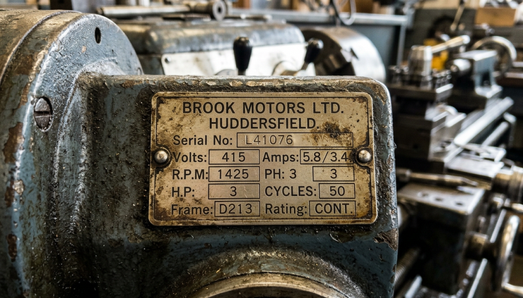
The first step is to read the motor plates. The nameplate gives the information that matters for drive selection, including power, voltage, current, and sometimes duty rating.
For the machines in this example, the motor plates show:
Machine | Motor power | Rated voltage | Rated current |
Lathe | 3 HP, about 2.2 kW | 400 to 440 V | 5 A |
Mill/drill | 0.75 kW | 415 V | 1.8 A |
The lathe motor is the larger load. If only one machine runs at a time, the shared VSD must be sized around the lathe, not the smaller mill/drill.
A 2.2 kW voltage-boosting VSD is the logical starting point to assess for the lathe. The final choice still depends on the drive’s output current and overload rating. The nameplate says the lathe motor is rated at 5 A, so the drive must comfortably support that current, including expected starting and machining loads.
The mill/drill is much smaller at 0.75 kW and 1.8 A. For that machine alone, a 0.75 kW single-phase to three-phase VSD may be suitable, assuming the motor and machine controls are compatible.
The key point is simple: do not size the drive from horsepower alone. Current rating and overload capacity are just as important.
Why a normal selector switch is not enough
A common idea is to wire one VSD to a selector switch, then switch the output between the lathe and the mill/drill. That approach can create serious problems if it is not designed correctly.
A VSD output is not the same as a normal three-phase supply. The drive is actively controlling the motor with a pulsed output. Opening or changing the motor connection while the drive is running can damage the drive, trip the system, or create unsafe machine behaviour.
A shared-drive arrangement needs more than a standard rotary switch. It needs a proper control scheme that prevents unsafe switching.
At a minimum, the design must provide:
Interlocking
The operator must not be able to change from one machine to the other while the VSD is enabled, while a run command is active, or while either motor is still rotating.
Machine selection before start
The selected machine should be confirmed before the VSD can start. Once running, selection should be locked out.
Correct start and stop logic
The lathe and mill/drill controls should command the VSD properly. The VSD should not be treated like an old direct-on-line contactor supply.
Reversing control through the VSD
Reversing should be controlled by the drive inputs or control system, not by switching output phases while energised.
Fault handling
If the VSD trips, stops, or loses power, the controls should return to a safe state.
This is why a shared VSD can be possible in theory, but risky in practice if treated as a plug-and-play job.
Each motor needs its own settings
A lathe motor and a mill/drill motor do not have the same current rating, overload requirement, acceleration time, braking behaviour, or speed range. A shared drive must know which motor it is controlling.
For the example above, the lathe motor is rated at 5 A. The mill/drill motor is rated at 1.8 A. If the VSD only uses the lathe settings for both machines, the smaller motor may not be protected properly. If the drive uses the mill/drill settings for the lathe, it may trip during normal lathe operation.
This is where selectable motor parameter sets matter.
Some drives allow more than one motor profile. The CM500 manual, for example, describes two selectable motor parameter sets. That feature could suit a shared-drive setup, because the operator or control system can select the correct motor settings before starting the chosen machine.
Before relying on that feature, the exact voltage-boosting model must be checked. Manuals often cover multiple drive variants, and not every function applies to every model in the same way.
The settings to confirm include:
Setting area | Why it matters |
Motor rated current | Protects each motor according to its nameplate |
Motor voltage and frequency | Matches the 400 to 415 V, 50 Hz motor rating |
Acceleration time | Prevents nuisance trips and harsh starts |
Deceleration time | Controls how the machine slows down |
Overload behaviour | Prevents overheating under heavy load |
Reverse command logic | Keeps reversing consistent and safe |
Stop mode | Decides whether the motor coasts or ramps down |
A shared drive should not depend on memory or guesswork. The machine selection and the motor parameter selection should agree every time.
The lathe sets the drive size
When only one machine runs at a time, the larger motor sets the minimum drive size. In this case, that is the 3 HP lathe motor.
A 3 HP motor is commonly treated as approximately 2.2 kW. The plate current is 5 A at 400 to 440 V. A 2.2 kW voltage-boosting VSD is the starting point, but it still needs checking against:
continuous output current
overload current and overload time
input current draw from the single-phase circuit
cooling and enclosure requirements
braking requirements
cable length and installation method
The available single-phase circuit rating must also be confirmed. A VSD that produces a 415 V three-phase output from single-phase input can draw significant current from the input side. The input circuit, protective device, cable size, and installation conditions all need review by a licensed electrician.
The drive also has to suit the motor’s condition. An older lathe motor may have insulation that was never designed with VSD output in mind. Many old motors run well on drives, but the motor should still be inspected and tested before installation. If the insulation is weak, a VSD can expose problems that were not obvious when the motor was running on a conventional supply.
Extra motors can change the answer
Older machines often have more than one electrical load. A lathe may have a coolant pump, lamp transformer, contactor coil, brake circuit, or control transformer. A mill/drill may have a separate feed motor or pump.
These loads matter because a VSD output is intended to feed a motor, not a whole machine full of mixed control gear.
Before selecting the drive, check whether either machine has:
coolant pumps
suds pump motors
power feed motors
control transformers
contactors and relays
electromagnetic brakes
work lights supplied from the machine wiring
foot brakes or safety switches wired into the old control circuit
Some of these items may need a separate supply. Some controls may need to be removed from the motor power circuit and rewired as low-voltage control inputs to the VSD. Some original machine functions may not be suitable to keep without redesign.
This is one reason the existing wiring must be inspected. It is not enough to look at the main motor plate and assume the rest will follow.
Braking and reversing need special care
Lathes bring two extra questions into the job: braking and reversing.
A lathe has rotating mass in the spindle, chuck, workpiece, belts, pulleys, and motor. Stopping that mass quickly pushes energy back toward the drive. If the deceleration time is too short, the VSD may trip on overvoltage unless the drive supports braking and the installation includes the right braking hardware.
Rapid braking may require:
a drive that supports braking
a correctly rated braking resistor
safe enclosure and heat management for the resistor
suitable stop settings
confirmation that the machine can handle the mechanical stress
Frequent reversing also needs attention. A lathe used for screwcutting, tapping, or production-style operations may reverse often. The VSD must be rated and programmed for that duty. The controls must prevent abrupt or conflicting commands.
For light hobby or maintenance use, a longer coast or ramp stop may be fine. For frequent reversing or short stopping times, the system needs more careful selection.
A good question to ask early is:
Does the lathe need rapid braking or frequent reversing, or will normal ramp stopping be acceptable?
The answer can change the drive choice and the control design.
One shared VSD compared with two separate drives
There is no single best answer for every workshop. The right setup depends on cost, convenience, safety, and how the machines are used.
One shared VSD | Separate VSDs |
Lower drive count | One drive per machine |
Needs machine selection and interlocking | Simpler wiring and control logic |
Needs correct motor parameter switching | Each drive keeps its own settings |
Only one machine can run at a time | Machines can be independent if the supply allows |
More design work | Easier fault finding |
Higher risk if switching is done poorly | Cleaner motor protection |
A shared VSD makes the most sense when both machines sit close together, only one will ever run at a time, and the control system is designed properly from the beginning.
Separate drives make more sense when the machines are used independently, when operators want normal controls on each machine, or when the cost of safe interlocking starts to outweigh the saving from using one drive.
For the lathe and mill/drill values above, the likely options are:
Use case | Option to assess |
Lathe only | 2.2 kW voltage-boosting VSD, subject to current and overload checks |
Mill/drill only | 0.75 kW single-phase to three-phase VSD |
Both machines, one at a time | Shared 2.2 kW voltage-boosting VSD with proper interlocking and motor parameter selection |
Both machines with simpler control | Separate VSDs sized for each motor |
The shared option is possible only if the drive model supports the needed functions and the controls are built to prevent misuse.

What to confirm before choosing the drive
Before quoting or ordering a drive, gather the details that decide the job. The motor plates are a strong start, but the full installation picture matters.
Confirm the following:
Available single-phase supply
Check the circuit rating, protective device, cable capacity, and whether the circuit is dedicated.
Motor plate details
Confirm voltage, current, power, frequency, connection type, and any duty rating.
Extra electrical loads
List coolant pumps, transformers, lights, brakes, contactors, and any auxiliary motors.
Machine wiring condition
Older wiring may be brittle, modified, or unsuitable for VSD control.
Motor condition
The lathe motor in this example is older, so insulation condition and bearings should be checked.
Required controls
Confirm start, stop, emergency stop, jog, reverse, speed control, and any existing interlocks.
Stopping and reversing duty
Decide whether normal ramp stop is enough, or whether rapid braking is required.
Installation environment
Consider dust, swarf, vibration, heat, coolant mist, and where the drive will be mounted.
This information lets the supplier and electrician confirm whether a 2.2 kW voltage-boosting VSD is suitable for the lathe, whether the 0.75 kW drive is suitable for the mill/drill, and whether a shared-drive arrangement is practical.
The safe answer is conditional
One VSD can run both a lathe and a mill/drill safely only when the system is designed around the larger motor, prevents live switching, applies the right motor settings, and integrates the start, stop, and reversing controls correctly.
For the example motor plates, the lathe sets the shared-drive size. A 2.2 kW voltage-boosting VSD is the right starting point to assess, provided its output current and overload rating suit the 5 A lathe motor. The smaller 0.75 kW mill/drill could use its own 0.75 kW single-phase to three-phase VSD if it is being converted on its own.
The shared-drive path can save hardware, but it adds control requirements. Separate drives cost more in drive hardware, yet they usually give simpler protection, easier operation, and fewer ways for something to be switched at the wrong time.
The next step is not to buy the biggest drive that looks close. Confirm the single-phase circuit rating, check for extra motors and transformers, decide on braking and reversing needs, then have the machine wiring and motor condition reviewed by a licensed electrician. Once those details are clear, the drive selection can be confirmed with confidence.


