.png)
Wireless Monitoring for 4–20 mA Instruments Connecting Pressure Level Flow and Analytical Transmitters
A plant can have excellent instruments and still poor visibility. A pressure transmitter may be wired correctly, calibrated, and feeding a local controller, yet the data may only be visible in one cabinet, one panel, or one control system. That limits how fast teams can respond to leaks, blocked filters, tank overfills, dosing issues, or process drift.
Wireless monitoring changes that without replacing the field instruments. Existing 4–20 mA pressure, level, flow, and analytical transmitters can often be connected to Monnit analogue-input sensors, then sent wirelessly to a gateway and monitoring platform. The result is wider access to process values, alarm notifications, trend history, and near real-time status from assets that were previously hard to see.

Why 4–20 mA instruments are good candidates for wireless monitoring
The 4–20 mA current loop remains one of the most common industrial signalling methods because it is simple, stable, and well suited to long cable runs. A transmitter converts a measured variable into current:
4 mA usually represents the lower range value
20 mA usually represents the upper range value
Values below or above that range may indicate a fault, underrange, overrange, or special diagnostic state, depending on the transmitter setup
This applies across many instrument types.
Instrument type | Common measurement | Example wireless use |
Pressure transmitter | Pump discharge pressure, filter differential pressure, vessel pressure | Alert when pressure drops, rises, or trends towards a blockage |
Level transmitter | Tank level, sump level, silo level | Track inventory or warn before overflow |
Flow transmitter | Water, chemical, air, gas, or slurry flow | Detect loss of flow or unexpected consumption |
Analytical transmitter | pH, ORP, conductivity, dissolved oxygen, turbidity | Monitor water quality or chemical dosing performance |
A Monnit analogue-input sensor acts as a wireless measurement point. It reads the analogue signal, then sends the data by radio to a Monnit gateway. From there, the data can be logged, displayed, and used for alerts.
This approach suits sites that want better visibility but do not want to alter the main control system. It can also help with remote utilities, water and wastewater assets, bulk storage, pump stations, treatment skids, and equipment supplied by third parties.
The main benefits of adding wireless monitoring
Wireless monitoring is not just about removing cable. The larger value comes from making process data easier to reach and easier to act on.
Better access to data
Many 4–20 mA signals terminate in a PLC, local display, chart recorder, or standalone controller. That can be enough for control, but not enough for operations, maintenance, compliance, or management reporting.
Wireless monitoring can make the same measurement visible from a dashboard, mobile device, or central monitoring point. A maintenance lead can see a pump pressure trend without opening a cabinet. An operations team can check tank level before sending a tanker. A utilities manager can review flow patterns across several remote sites.
Near real-time alarms
A local gauge only helps when someone is nearby. Wireless monitoring can send alerts when values pass a threshold, fail to change, move too quickly, or fall outside the expected range.
For example:
A falling pressure trend may suggest a pump fault or pipe leak
A rising differential pressure may point to a blocked filter
A high tank level may require a transfer pump to start
A pH value outside limits may call for dosing adjustment
A zero flow condition may indicate a closed valve or failed pump
The reporting interval matters. Battery-powered wireless sensors often trade reporting speed against battery life, so “real time” should be set to match the risk. Critical alarms may need short intervals. Slow-changing tank levels can usually report less often.
Lower installation cost on difficult assets
Running new signal cable can be expensive where instruments are far away, buried, elevated, or located across roadways and process areas. Wireless sensors can reduce trenching, conduit, shutdown time, and panel work.
That is especially useful when the goal is monitoring rather than closed-loop control. The control loop can stay as it is, while the wireless sensor provides a parallel visibility layer.
Trend history for maintenance decisions
A single alarm tells a team something has happened. A trend shows how it happened.
Wireless data logging helps reveal patterns such as:
Gradual pump wear
Seasonal inflow changes
Batch-to-batch dosing variation
Recurring high-level events
Sensor drift or fouling
Flow imbalance between lines
These patterns support better maintenance timing and fewer unnecessary site visits.
How the connection works
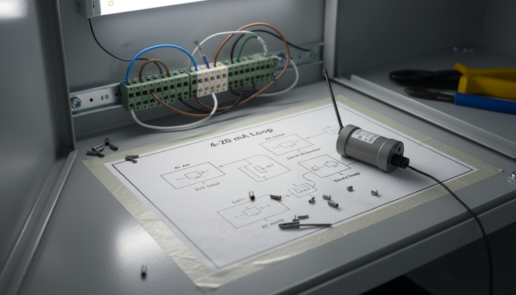
A 4–20 mA loop is a series circuit. The same current flows through the transmitter, power supply, and receiving input. That detail matters because a current input cannot simply be connected in parallel like a voltmeter.
There are three common connection cases.
A new monitoring-only loop
If the transmitter is not already connected to a PLC or controller, the Monnit analogue-input sensor can be wired as the receiving input for the loop, provided the sensor type supports 4–20 mA input and the loop has a suitable power supply.
A typical arrangement includes:
24 V DC loop supply, or another supply approved for the transmitter
Two-wire or four-wire transmitter
Monnit analogue-input sensor set for current input
Correct polarity through the loop
Suitable enclosure and cable glands for the environment
An existing loop with one receiver
If the transmitter already feeds a PLC or display, the safest design is often to use a signal isolator or current splitter. This device takes the existing 4–20 mA signal and creates a second isolated 4–20 mA output for the wireless sensor.
This avoids several problems:
Added loop burden that may exceed the power supply capability
Ground loops between systems
Unplanned effect on the control input
Faults on the monitoring side affecting the control side
Series wiring may be possible in some installations, but it must be checked carefully. Every current input adds resistance, called burden, and the loop power supply must have enough voltage to drive the transmitter plus all input burdens at 20 mA.
A loop with an available retransmission output
Some control equipment, displays, and analytical transmitters provide a retransmitted 4–20 mA output. This is often an ideal source for wireless monitoring because it is already designed to feed another device.
Check whether the retransmitted signal is active or passive, isolated or non-isolated, and scaled the same way as the primary measurement.
Step-by-step integration guide
Use a controlled work process and follow site electrical, instrumentation, and safety procedures. The steps below describe the typical technical path.
1. List the instruments and measurements
Start with a simple register of the transmitters to be monitored.
Record:
Tag number
Measured variable
Range, such as 0 to 1,000 kPa or 0 to 5 m
Output signal, normally 4–20 mA
Existing receiver, such as PLC, display, recorder, or controller
Power supply voltage
Hazardous area classification, if relevant
Location and enclosure rating
This avoids guesswork later. It also helps decision-makers see which measurements give the best return.
2. Confirm the Monnit sensor input type
Select a Monnit analogue-input sensor that matches the signal. For current loops, use a model or input configuration rated for 4–20 mA current input.
Do not assume a voltage input can read a current loop directly. Some systems use a precision resistor to convert current to voltage, such as 250 ohms to create 1–5 V from 4–20 mA, but this must be designed correctly and allowed for in the loop burden. If a direct 4–20 mA input is available, use it.
3. Choose the integration method
Pick one of these approaches:
Existing situation | Preferred connection method |
No existing receiver | Wire the Monnit sensor as the loop receiver |
Existing PLC or controller input | Use an isolated signal splitter, or confirm series wiring is acceptable |
Available retransmission output | Connect the Monnit sensor to that output |
Critical control loop | Use isolation so monitoring cannot disturb control |
Hazardous area loop | Use approved barriers, isolators, and equipment for the area |
For control or safety-related loops, do not make the wireless sensor a single point of failure.
4. Check loop power and burden
A current loop needs enough voltage to push 20 mA through all devices in series. The transmitter data sheet will state its minimum operating voltage. Each receiving input and barrier adds burden.
The basic check is:
Available loop voltage must exceed transmitter voltage requirement plus all voltage drops at 20 mA.
If the numbers are close, use a signal isolator or a separate output rather than adding another series device.
5. Plan the physical installation
Wireless does not remove the need for good field practice. Place the sensor where it is protected from heat, water ingress, vibration, chemical exposure, and mechanical damage.
Also check radio path to the gateway. Metal tanks, switchrooms, concrete pits, and dense pipework can reduce wireless signal strength. A gateway location with height and fewer obstructions usually performs better.
6. Isolate and wire the signal
Before opening the loop, follow the site isolation process. Confirm whether interrupting the signal will affect control, alarms, or reporting.
For a typical 4–20 mA current input, wire the sensor in the correct polarity according to the Monnit documentation and the loop design. Keep instrument cable screens and earths consistent with site standards. Avoid creating multiple earth points that can lead to noise or ground loop issues.
Label the terminals and update drawings as soon as the work is complete.

7. Scale the measurement
The wireless platform needs to convert milliamps into engineering units. Use the transmitter range from the instrument configuration, not only from the nameplate if the device is programmable.
A common linear scaling formula is:
`Measured value = ((mA - 4) / 16) × span + lower range value`
For a pressure transmitter ranged 0 to 1,000 kPa:
4 mA equals 0 kPa
12 mA equals 500 kPa
20 mA equals 1,000 kPa
Analytical transmitters may need extra care. A pH transmitter may be scaled 0 to 14 pH, 2 to 12 pH, or another range chosen for the process. Conductivity and turbidity ranges can vary widely.
8. Set reporting intervals and alarms
Set the reporting interval to match the process speed and risk.
Fast-changing values may need more frequent reporting. Slow tank levels may not. Shorter intervals can reduce battery life, so choose a setting that gives useful visibility without unnecessary transmissions.
Configure alarms for:
High and low process values
Rate of change where useful
No change when change is expected
Sensor communication loss
Low battery, if battery powered
Out-of-range analogue values
Use sensible alarm delays to avoid nuisance alerts from short spikes.
9. Test at known points
Test the full path, not just the wiring.
Use a loop calibrator, transmitter simulator, or controlled process condition to check values near 4 mA, 12 mA, and 20 mA. Confirm that the wireless dashboard shows the correct engineering units and that alarms trigger as expected.
For existing loops, also confirm that the PLC or controller still reads correctly after the monitoring sensor or splitter is installed.
10. Document and hand over
Record the final wiring, scaling, alarm limits, reporting interval, sensor ID, gateway, and battery details. Store this with the instrument loop sheet or asset record.
Good documentation prevents future technicians from removing or bypassing the wireless sensor because it looks unfamiliar.
Common challenges and practical solutions
Challenge | What can go wrong | Practical solution |
Loop burden is too high | The transmitter cannot reach 20 mA, or readings clip high | Use an isolated splitter or retransmitted output |
Current input connected in parallel | Readings become unstable or incorrect | Wire current inputs in series, or use a splitter |
Wrong scaling | Dashboard values look plausible but are wrong | Confirm transmitter range and apply engineering-unit scaling |
Poor wireless signal | Missed reports or delayed alarms | Move the gateway, improve line of sight, or use a stronger antenna arrangement where supported |
Electrical noise | Readings fluctuate unexpectedly | Check shielding, earthing, cable routing, and isolation |
Analytical sensor drift | Wireless data shows a slow error trend | Keep normal calibration and cleaning routines in place |
Battery changes too frequent | Maintenance load increases | Adjust reporting interval and alarm settings to suit the process |
Hazardous area requirements | Equipment may not be suitable for the location | Use approved barriers, enclosures, and devices rated for the area |
The biggest mistake is treating the wireless input as just another pair of wires. It is part of an electrical measurement loop. The original loop function must stay protected.
Where wireless 4–20 mA monitoring works well
Wireless monitoring is a strong fit when the measurement matters, but hardwired integration is too costly or slow.
Good examples include:
Remote water tanks and pump stations
Chemical bulk storage
Filter differential pressure
Wastewater lift stations
Cooling water flow
Boiler feedwater or condensate monitoring
Trade waste pH or conductivity
Temporary monitoring during commissioning or troubleshooting
Legacy panels without modern data access
It also helps when several stakeholders need the same data. Engineering may care about the loop accuracy. Maintenance may care about drift and failure. Operations may care about alarms. Management may care about production loss, water usage, or service response. A wireless monitoring layer can serve all of those needs without forcing every signal into a major control system upgrade.

Design tips for a reliable installation
A reliable installation starts before anyone lands a screwdriver on a terminal.
Keep these points in mind:
Protect the control loop
If the signal feeds control, dosing, safety interlocks, or compliance reporting, use isolation unless the engineering review confirms another method is safe.
Use the right enclosure
Outdoor installations need suitable IP-rated enclosures, UV-resistant fittings, and cable glands matched to the cable type.
Name sensors clearly
Use plant tags and plain descriptions, such as `PT-204 Filter Outlet Pressure`. Clear names reduce alarm confusion.
Avoid alarm overload
Start with a small number of meaningful alarms. Add more after reviewing trend behaviour.
Keep calibration separate from wireless setup
The wireless sensor reports the signal it receives. It does not fix a poorly calibrated transmitter.
Test after any loop change
A small wiring or scaling change can affect the whole measurement chain.
What success looks like
A successful installation should be almost boring. The existing transmitter still works. The PLC or display still reads correctly. The Monnit analogue-input sensor reports stable values in the right units. Alarms arrive when tested. Trend data builds over time. Technicians can understand the wiring when they open the enclosure later.
That is the real value of adding wireless monitoring to 4–20 mA instruments. It extends the usefulness of pressure, level, flow, and analytical transmitters already installed across the site. It gives decision-makers better access to data, while giving engineers a practical path that respects the original loop design.
Start with one or two high-value measurements, prove the wiring method and reporting setup, then expand to the instruments where visibility will reduce risk, save site visits, or catch faults earlier.


